Research Article - Onkologia i Radioterapia ( 2022) Volume 16, Issue 8
Pre-treatment verification of carcinoma breast VMAT plan based on mono-isocentric technique: Assessment of the combined fields feature of new 2D MatriXX arrays resolution
Raoui Yasser1*, Sebihi Rajaa1, Teerthraj Verma2, VP Pandey3, Herrassi Yassine4, Elghalmi Mohammed5, Chouib Fatima Ezzahra6, Chehab Fatim Zahra1, Elghemary Nihad6, El Ouardy Khalid7 and Erraoudi Mourad12Department of Radiotherapy, King George Medical University, Lucknow, Uttar Pradesh, India
3Department of Medical Physics, Hind Institute of Medical Sciences, Barabanki, Uttar Pradesh, India
4Iba Dosimetry Schwarzenbruck, Germany
5Department of Physics, Faculté of Sciences, Ibn Tofail University in Kénitra, Morocco
6Biomedical School Mohammed VI University of Health Sciences, Casablanca, Morocco
7Department of Physics, University of Mohammed 1st , Oujda, Morocco
Raoui Yasser, Department of Physics, Faculty of Sciences, University Mohammed V in Rabat, Morocco, Email: yasser@gmail.com
Received: 10-Aug-2022, Manuscript No. OAR-22-71578; Accepted: 28-Aug-2022, Pre QC No. OAR-22-71578 (PQ); Editor assigned: 12-Aug-2022, Pre QC No. OAR-22-71578 (PQ); Reviewed: 26-Aug-2022, QC No. OAR-22-71578 (Q); Revised: 27-Aug-2022, Manuscript No. OAR-22-71578 (R); Published: 28-Aug-2022
Abstract
Objective: Our work aims to verify the Mono-Isocentric technique-based Volumetric Modulated Arc Therapy (VMAT) plan for carcinoma breast and regional nodes employing the new 2D arrays MatriXX Resolution from IBA dosimetry systems, Schwarzenbruck, Germany loaded with the combined field feature.
Materials and Methods: This study included 12 Mono Iso-centric VMAT plans for breast cancer with supraclavicular and axillary nodes. The radiotherapy planning was performed by the Monaco TPS (5.51 Elekta Limited, Crawley, UK) following the departmental planning protocols employing 6 MV photons using the XVMC algorithm for Dose calculation. The plans were optimized using an arc geometry with 25 increments in gantry angle spacing between control points with a 3 mm resolution dose grid size and 1% per calculation dose to medium, minimum segment width 0.5 cm and high fluence smoothing. These plans were delivered clinically by an Elekta Infinity linear accelerator equipped with Agility 160- leaf MLC (Elekta Limited, Crawley, UK). Two CT scans of the MatriXX resolution inserted in the Mini Phantom R were acquired using a CT simulator (GE discovery (General Electricals, USA). Out of these two scans, the first one is taken as the default CT and the second one as the extended CT, to use for large fields combination.
In this study, normal and combined fields were compared using myQA patients’ software (IBA Dosimetry, Germany) based on the gamma index analysis and point dose measurements with the ion chamber CC04 according to IAEA Protocol TRS398.
Results: The new 2D array detector provided good agreement for dose maps without combined field features over the field lengths ranging from 22 cm to 24 cm and excellent agreement for maps with combined fields for lengths ranging from 24 cm to 28 cm. VMAT Clinical cases passed with more than 95% for the set criteria of 3% DD & 3 mm. The absolute point dose measurement agreement was found to be more than 98%.
Conclusion: The MatriXX Resolution is a convenient, fast, robust, and practical tool for routine large-field pre-treatment verification in IMRT, VMAT and other advanced techniques.
Keywords
Patient-Specific Quality Assurance, Combined Field, My QA Software, 2D Array detector
Introduction
Breast cancer is one of the most commonly diagnosed cancers, contributing up to 30% of all new cancer cases in women placing a significant burden on the workload of most radiotherapy departments [1]. Radiotherapy is an essential component in the local and regional management of breast cancer, reducing local recurrence in higher-risk patients and improving adjuvant survival.
The topology of this case is complex and achieving both the dose homogeneity to the target volume and dose constraints to the surrounding tissues poses great challenges in radiotherapy treatment planning.
In recent years Intensity-Modulated Radio-Therapy (IMRT) and Volumetric Modulated Arc Therapy (VMAT) have been adopted for the use of breast or chest wall treatments with supraclavicular and axillary nodes and they proved to be more suitable for creating an optimal treatment plan [2].
A dualâ?isocenter approach accommodates patients with larger target volumes, but prolonged treatment time may introduce uncertainty in the dose at the matching plane due to daily setup variations.
Multi-partial arc VMAT can provide plans with better dose homogeneity within the target and helps in achieving dose constraints for Organ at Risk (OARs).
Furthermore, by combining continuous gantry rotation, variable dose rate, and dynamic beam modulation, highly conformal dose distributions are achieved [3,4]. Patient-specific quality assurance is required for increasingly complex VMAT plans with sharp gradients with Patient-Specific Quality Assurance Protocol (PSQA). Pre-treatment verification is fundamental for detecting any discrepancies between planned and delivered doses in all VMAT plans [5]. This is usually accomplished by applying the treatment plan to a dosimetric phantom and comparing the measured and calculated phantom dose distributions using the Gamma Index (GI).
Low et al. introduced the method of quantitatively comparing measured and calculated dose maps [6]. Absolute dose distribution measurements in a 2D plane or 3D geometries can be performed using detector arrays made up of ion chambers or diodes. The present study was taken to investigate the performance of the new 2D detector from IBA Dosimetry, the MatriXX Resolution, and a Mini Phantom R in large fields with and without the feature combined field in my QA software for Mono Iso-centric VMAT plans in case of breast cancer with supraclavicular and axillary nodes [7,8].
Materials and Methods
In the present study, 12 patients of ca breast including the supraclavicular and axillary nodes were studied to achieve the aim of this study. All the 12 patients were planned using MonoIso-centric VMAT techniques. First, CT scans (Discovery, General Electric, USA) of all the 12 patients were acquired simulating the institutional guidelines for VMAT planning (Table 1). The slice thickness of this CT acquisition was 2.5 mm done on 120 KV. Then acquired CT image set was transferred to the contouring workstation where different organs including the body and targets were delineated. Also, the CT to ED curve, generated with the help of CIRS electron density phantom was applied in these 12 patients’ VMAT planning using Monaco TPS (V 5.5.1, Elekta Medical system, Sweden) utilizing the XVMC algorithm. Table 1 shows the constraints and the parameters applied to these.
Tab. 1. Optimization parameters used to plan VMAT cases
| Parameter | Value |
|---|---|
| Beamlet width | 0.3 cm |
| Surface Margin | 0.2 cm |
| Autoflash Margin | 1.5 cm |
| Target Margin | tight 2 mm |
| Arcs Geometry | 2 Arcs: 1 Auto, 2 Fixed only on the breast |
| Increment | 25 Deg |
| Sequential | 180 CP |
| Collimator | 0 Deg |
| Leaf Width | 0.5 mm |
| Fluence Smoothing | High |
The VMAT plan for each of the 12 patients was optimized using the Monaco planning system with the constrained mode and the parameters listed in the table-1 below:
An auto-flash margin option was used for VMAT plans and the Multi-Leaf Collimator (MLC) leaves were opened outside of the body contour.
A 6 MV photon energy and Agility MLC were used to create the Monaco VMAT treatment plans. The final dose was calculated using X-ray Voxel Monte Carlo (XVMC) with 0.3 cm voxel size and 1% calculation uncertainty. To achieve agreement with the physician prescription and OAR tolerances, IMRT constrained were used as shown in Table 2.
Tab. 2. Planning constraints used in VMAT cases using Monaco TPS
| Structure | Cost Function | Parameters |
|---|---|---|
| Breast PTV | Target Penalty | Prescription 50 Gy |
| Quadratic Overdose | Minimum Volume Dose (%)=95 | |
| Regional Nodes PTV | Target penalty | Prescription 50 Gy |
| Minimum Volume Dose (%)=95 | ||
| Quadratic Overdose | Maximum Dose (Gy)=54.5 | |
| RMS =0.05 | ||
| Spinal Cord +0.5 cm | Serial | Equivalent Uniform Dose (Gy)=20 |
| Power Low Exponent =12 | ||
| Heart | serial | Equivalent Uniform Dose(Gy)=8 |
| Power Low Exponent=16 | ||
| Oesophagus | parallel | Reference Dose(Gy)=30 ; Mean Organ Damage(%)=40 |
| Power Low Exponent=3 | ||
| Humeral Head | serial | Equivalent Uniform Dose(Gy)=28 |
| Power Low Exponent=12 | ||
| Liver | parallel | Reference Dose (Gy)=20 ; Mean Organ Damage(%) =40 |
| Power Low Exponent=4 | ||
| Homolateral Lung | Parallel | Reference Dose(Gy)=20 ; Mean Organ Damage(%)=27 |
| Power Low Exponent=4 | ||
| serial | Equivalent Uniform Dose(Gy)=18 | |
| Power Low Exponent=1 | ||
| serial | Equivalent Uniform Dose(Gy)=37 | |
| Power Low Exponent=12 | ||
| Overdose DVH | Objective Dose(Gy)=30 | |
| Maximum Volume(%)=19 | ||
| LARYNX | Serial | Equivalent Uniform Dose(Gy)=37 |
| Power Low Exponent=12 | ||
| parallel | Reference Dose(Gy) 30 ; Mean Organ Damage(%)=6 | |
| Power Low Exponent= 4 | ||
| Body | Quadratic Overdose | Maximum Dose(Gy)=50 |
| RMS=0.3 | ||
| Quadratic Overdose | Maximum Dose(Gy)=35 | |
| RMS=1.2 | ||
| Quadratic Overdose | Maximum Dose(Gy)=25 | |
| RMS=0.04 | ||
| Maximum | Maximum dose(Gy)=54.5 |
Generation of QA plan in the TPS
Firstly, CT scan images of all the patients were transferred to Monaco TPS. After this, a relative electron density of 1.016 and 1.030 was assigned to the RW3 MiniPhantom-R and MatriXX Resolution detector respectively. After optimization, the VMAT plan was completed shown in figure 1, the patient-specific quality control (QA plan) was performed using the scanned MatriXX for both the cases at the planning system level, next, and exported the plan to the Mosaiq record and verify system.
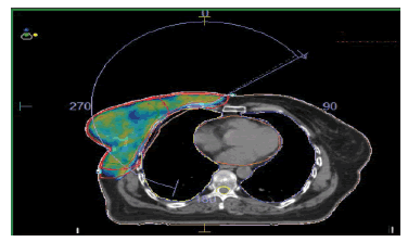
Figure 1: Dose distribution and coverage planned using VMAT Technique
Method of measurement
To generate the measurement maps without the combined field feature, the centre of the Matrixx Resolution was aligned with the isocenter of the linac and then delivered the Arcs of the VMAT plan using Integrity MLC (Elekta Inc.). The recorded dose planes on a detector are shown in figure 2.
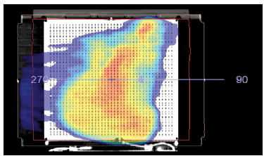
Figure 2: QA plan for field without combined field
As a second step, we aligned the isocenter to the 3rd row (a marker is printed in the Mini Phantom R) of the sensors from the edge of the Matrixx Resolution detector.
For the maps with the combined field feature, the first measurements were performed at 0° of the devices and the Arcs of the plan were delivered. After this device was rotated to 180°, aligning the isocenter with the centre of the 3rd row and delivering the arcs. The dose maps of the combined field thus obtained are shown in Figure 3.
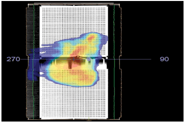
Figure 3: Dose map for a plan with a combined field
MatriXX resolution
MatriXX Resolution is a 2D detector used in dose measurement for quality assurance in external beam radiation therapy.
The device is intended to be used with the myQA software, for both the verification of patient treatment plans (Patient QA) and the treatment machine performance (Machine QA).
The MatriXX Resolution detector consists of a 2D sensor array and electronics. It has a higher resolution and the option of wireless operation compared with other MatriXX detectors from IBA Dosimetry. Figure 4 shows the pictorial representation of MatriXX resolution.
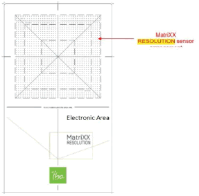
Figure 4: Outlay of detectors and electronics in MatriXX Resolution
Working on MatriXX resolution
The sensors of the MatriXX resolution are designed in a unique way of vented pixel ionization chambers. Each of these chambers has its measurement channel. When chambers are irradiated, the air inside the chambers gets ionized. Thus the released charges are separated with the help of an electrical field applied between the bottom and the top electrodes. The flow of charged constituting current is proportional to the dose rate and is measured and digitized by analogy to digital converters. The myQA patient software analyses the measured 2D dose distribution and compares it with the one calculated by the TPS.
The MatriXX Resolution has 1521 chambers arranged in a 39 cm×39 cm grid matrix that cover an active field of 25.3 cm×25.3 cm at 100 cm SDD. The effective point of measurement of the central chamber is positioned at the isocenter. The distance between the individual chambers is 6.5 mm from centre to centre.
The Combined Fields Feature
The Combine Fields tool, which combines two fields in the longitudinal direction, enables performing Patient QA for large fields. For a field larger than the detector sensor area, two measurements are taken, an upper and a lower section, with a small amount of overlap to ensure full coverage. Figure 5 shows the matrix assembly with an isocenter location.
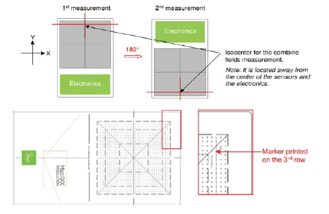
Figure 5: Demonstration for the 3rd ROW matrix detector
The two field sections are combined into the completed field by applying the Combine Fields wizard.
Point Dose Measurement
Also, point dose measurement was done for the same clinical cases, the TPS calculated dose on the MiniPhantom R and the ionization chamber employed in this study was CC04 (IBA Dosimetry, Germany) connected to IBA DOSE 1 electrometer. The chamber has a cavity length of 3.6 mm, a diameter of 2.0 mm, a volume of 0.04 cm3 , and a wall thickness of 0.070 g per cm2 , temperature and pressure were measured and the dose determination was performed according to IAEA TRS 398.
Statistical Analysis
Gamma Index
The gamma index criteria are the gold standard QA tool for assessing the agreement between TPS calculated data and phantom measured one in the case of VMAT planning, as well [9]. It was developed to combine the two previous assessment criteria viz Dose Difference (DD) and Distance to Agreement DTA. This important quantity is essential in confirming the correct delivery of the complex dose distributions seen in modern IMRT [10].
Results
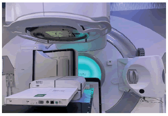
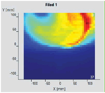
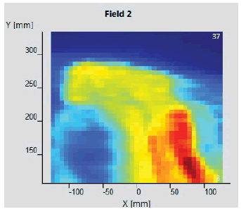
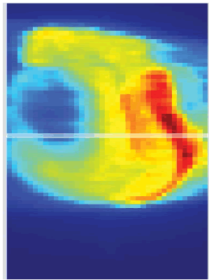
The initial setup of the matrix resolution detector is shown in figure 6. Twelve patients were undertaken for the study and the gamma measurement with and without combined field measurement was performed using IBA MatriXX 2D array detector. The dose maps with lower, upper and combined fields were measured as shown in Figures 7-9. Figures 10 and 11 show my QA results using a combined field feature to analyse the gamma index [11].
Figure 6: Initial Setup for the MatriXX Resolution
Figure 7: Lower Measurement
Figure 8: Upper Measurement
Figure 9: The Combined fields
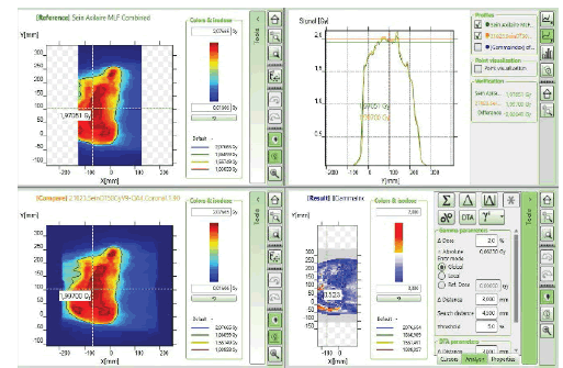
Figure 10: myQA Patient, Gamma Index comparison for the plan with the combined field feature.
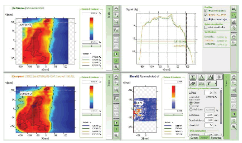
Figure 11: myQA Patient, Gamma Index comparison for the plan without the combined field feature
For the 3% per 3 mm DTA (Dose to Agreement) parameter the tumour length greater than 25 cm shows good agreement in results with the combined field tool and for less than 25 cm tumour length size, the gamma index value shows good agreement even with the single field analysis tool. Figure 12 shows the G.I results obtained using the combined tool are greater than 95% for tumour length size greater than 25 cm.
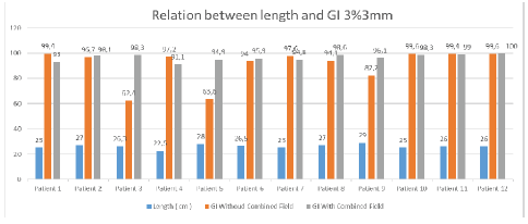
Figure 12: Relation between gamma index and length of tumour at 3% per 3mm criteria
At 3% per 3 mm, DTA and tumour length 27 cm gamma index passing using combined field tool was found to be 98.1% compared to the gamma index without combined field tool which was found to be 96.7%. For 26.3 cm tumour length gamma index passing percentage without using the combined field tool was found to be 62.4% compared to using the combined field tool which was recorded at 98.3%. Similarly, for 28 cm tumour length, the result obtained without using a combined field was 63.6% which showed a good agreement of 94.9% when using the combined field tool. For a smaller tumour length of 22.5 cm, the results obtained without using the combined field tool were better (97.2 %) than considering the analysis using the combined field tool resulting in a lowering of the gamma passing percentage of 91.1%.
For 3% per 2 mm DTA parameters, the gamma index obtained for tumour length sizes near 25cm shows comparable results using a combined tool and without combined tools. Again for tumour length greater than 25 cm, Gamma Index passing percentage will be better while opting combined field tool and for a length, less than 25 cm better Gamma Index passing percentage was obtained without using the Combined tool. Figure 13 shows the result analysis for 3% per 2 mm DTA parameters for gamma index analysis for varying tumour length using combined field and without the combined field tool option in myQA software [12].
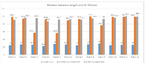
Figure 13: Relationship between gamma index and length of tumour at 3% per 2 mm criteria
Point dose assessments in MiniPhantom R setup were performed as shown in figure 14 for all the clinical cases studied in this present research work with breast cases and supraclavicular involvement following TRS 398 protocol.
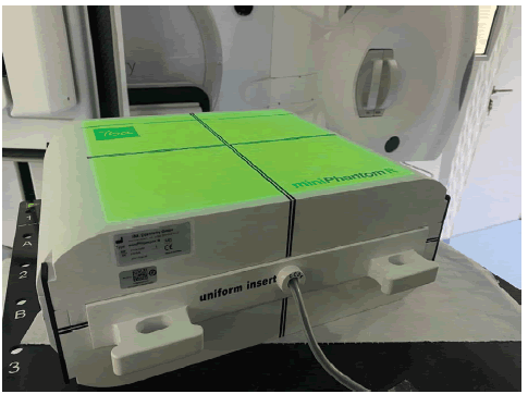
Figure 14: Point dose measurement setup using CC04 Chamber
A maximum variation of 1.6% was observed in all 12 cases. The point dose difference criteria were acceptable as per the recommendations for all clinical cases investigated here [13]. Table 3 shows the data obtained while performing point dose measurement using mini R phantom and CC04 ionization chamber.
Tab. 3. Assessment of point dose differences in calculated and measured values
| Calculated Dose [Gy] | Measured Dose [Gy] | Standard Deviation | |
|---|---|---|---|
| Patient 1 | 1.484 | 1.485 | 0.0006 |
| Patient 2 | 1.849 | 1.849 | 0.001 |
| Patient 3 | 1.733 | 1.723 | 0.0058 |
| Patient 4 | 1.469 | 1.46 | 0.006 |
| Patient 5 | 1.736 | 1.757 | 0.012 |
| Patient 6 | 1.522 | 1.54 | 0.0116 |
| Patient 7 | 1.698 | 1.68 | 0.0107 |
| Patient 8 | 0.495 | 0.502 | 0.014 |
| Patient 9 | 1.624 | 1.614 | 0.0061 |
| Patient 10 | 1.654 | 1.65 | 0.0024 |
| Patient 11 | 1.903 | 1.92 | 0.0088 |
| Patient 12 | 1.613 | 1.64 | 0.0164 |
For tumour size less than 25 cm using the combined tool results in lower Gamma Index passing results for both DTA parameters of 3% per 3 mm & 2% per 2 mm. For all the plans, Gamma evaluation was performed using Global mode with the preferred dose to agree on passing criteria. The term “Global” indicates maximum dose normalization in a given volume. The threshold value of 5% is selected in every plan analysis to nullify the contribution of background scattered noise.
Discussion
At slightly strict Gamma index passing criteria i.e. 3% per 2mm, the results obtained for tumour size 25 cm was 98.3% without using the combined field tool compared to a passing rate of 91% while using the combined field feature [14]. For tumour size 22.5 cm, the results without using the combined field option were 91.1% however it lowered downs to 86.8% while used with the combined field tool. For the tumour length of 29 cm, the Gamma index passing without using the combined tool option was 76.6% while the passing rate reached 93% when the combined field tool option for analysis was employed.
The Global dose gamma analysis resulted in a higher passing rate for tumour length greater than 25 cm while using a combined field feature other than without a combined field feature. The action limits of thresholds in all analyses were kept constant at 5% which reduces the large number of low-dose regions, which may result in an inflated passing rate when evaluated with the global gamma analysis. The active field of the detector was 25.3 cm×25.3 cm and this is taken as the primary reason for good agreement with the results obtained for tumour lengths up to 25 cm even without using the combined field tool option.
For larger tumour lengths greater than 25 cm, if the combined field option would not include for analysis then there is a quite high chance of losing the data outside the active area which may result in disagreement between the calculated and measured fluence. In the global mode analysis methodology maximum of the normalized volume was considered for comparison which makes the greater size tumours more susceptible to being associated with the errors. Analysis without using combined tool features in case of larger length compared to active detector size leads to lowering of gamma index passing.
The chances of error increase for tumour size less than 25 cm using the combined tool option as there is always more probability of overlap of data during exposure to the active detector regions and results in compromising the scatter contribution which leads to lowering of gamma passing percentage. It is always advisable to use the combined field tool feature for tumour lengths greater than 25 cm which resulted in good agreement with the planned fluence.
Point dose assessment in a long field at an isocenter using ionization chamber CC04 shows good agreement with the calculated TPS values and shows a maximum variation of 1.64% in one case which is well accepted as per the recommendations. The concurrence of point dose & gamma index passing gives a good idea of the usefulness of the combined field tool feature in long tumour structures
Conclusion
The MatriXX Resolution was found to be a handy, fast, robust and practical tool for the routine pre-treatment verification of large fields. The combined field feature is a unique tool for analysis of the gamma index for tumour length greater than 25 cm and shows promising results.
References
- Kinhikar RA, Pandey VP, Jose RK, Mahantshetty U, Dhote DS, et al. Investigation on the effect of sharp phantom edges on point dose measurement during patient-specific dosimetry with Rapid Arc. J Med Phys/Assoc Med Phys India. 2013; 38:139.
- Khalid EO, Mustapha Z, Yassine H, Raoui Y, Pandey VP. Validation of Monaco TPS for an ELEKTA synergy MLCi2: Using gamma index for eElekta full package beams. Mater Today: Proc.2021; 45:7685-7689.
- Raoui Y, Herrassi Y, Elouardy K, Sebihi R, Ayad M, et al. Beam Modeling in Commercial Treatment Planning System for IMRT and VMAT performance with an Elekta MLCI 2 Multileaf Collimator. Iran J Med Phys. 2021; 18:452-460.
- Low DA, Dempsey JF. Evaluation of the gamma dose distribution comparison method. Med Phys. 2003;30:2455-2464.
- Teoh M, Clark CH, Wood K, Whitaker S, Nisbet A. Volumetric modulated arc therapy: a review of current literature and clinical use in practice. Br J Radiol.2011;84:967-996.
- Kaneko A, Sumida I, Mizuno H, Isohashi F, Suzuki O, et al. Comparison of gamma index based on dosimetric error and clinically relevant doseâ??volume index based on three-dimensional dose prediction in breast intensity-modulated radiation therapy. Radiat Oncol. 2019; 14:1-1.
- Jin X, Yan H, Han C, Zhou Y, Yi J, et al. Correlation between gamma index passing rate and clinical dosimetric difference for pre-treatment 2D and 3D volumetric modulated arc therapy dosimetric verification. Br J Radiol.2015;88:20140577.
- Miften M, Olch A, Mihailidis D, Moran J, Pawlicki T, et al. Tolerance limits and methodologies for IMRT measurementâ?based verification QA: recommendations of AAPM Task Group No. 218. Med Phys. 2018;45:53-83.
- Low DA, Moran JM, Dempsey JF, Dong L, Oldham M. Dosimetry tools and techniques for IMRT. Med Phys. 2011; 38:1313-1338.
- Abbas AS, Moseley D, Kassam Z, Kim SM, Cho C. Volumetricâ?modulated arc therapy for the treatment of a large planning target volume in thoracic oesophagal cancer. J Appl Clin Med Phys. 2013; 14:192-202.
- Wang X, Zhang X, Dong L, Liu H, Wu Q, et al. Development of methods for beam angle optimization for IMRT using an accelerated exhaustive search strategy. Int J Radiat Oncol* Biol* Phys 2004;60:1325-1337.
- Stathakis S, Myers P, Esquivel C, Mavroidis P, Papanikolaou N. Characterization of a novel 2D array dosimeter for patientâ?specific quality assurance with volumetric arc therapy. Med Phys. 2013; 40:071731.
- Nasseri S, Bahreyni MH, Momennezhad M, Gholamhosseinian H, Shahedi F, et al. Dosimetric verification of IMRT and 3D conformal treatment delivery using EPID. Appl Radiat Isot.2022:110116.
- Jomehzadeh A, Shokrani P, Mohammadi M, Amouheidari A. Assessment of a 2D electronic portal imaging devices-based dosimetry algorithm for pretreatment and in-vivo midplane dose verification. Adv Biomed Res. 2016;5.
