Research Article - Onkologia i Radioterapia ( 2025) Volume 19, Issue 1
Halcyon Unveiled: Commissioning the Future of Cancer Care at the International Center of Oncology Benguerir (CIOB)
Abour Mohamed1*, Mohamed Bencheikh1, Elghalmi Mohammed2 and Elmahjoub Chakir22Physics of Materials and Subatomic Laboratory, Faculty of Science Kenitra, Ibn Tofail University Kenitra, Morocco
Abour Mohamed, LSIB Laboratory, Faculty of Sciences and Technologies Mohammedia, Hassan II University of Casablanca, Mohammedia, Morocco, Email: mohamedabour88@gmail.com
Received: 19-Feb-2025, Manuscript No. OAR-25-165691; , Pre QC No. OAR-25-165691; Editor assigned: 21-Feb-2025, Pre QC No. OAR-25-165691; Reviewed: 07-Mar-2025, QC No. OAR-25-165691; Revised: 21-Apr-2025, Manuscript No. OAR-25-165691; Published: 28-Apr-2025
Abstract
Background: Based on the Ring Delivery System (RDS), varian medical systems has unveiled HalcyonTM 4.0, a revolutionary medical linear accelerator with 4RPM. It has 6MV FFF photon energy, making it a real IGRT machine. It provides a very fast kV-iCBCT option along with regular planar and MV-CBCT imaging. This helps create better images and improves how we see soft tissues. A particular stacked and staggered double-layer MLC that allows for maximum modulation with minimal radiation leakage shapes the field portals. Our first Halcyon 4.0 machine was just put into service. This work's objective was to methodically examine a number of parameters of a recently installed Halcyon 4.0 linear accelerator. Materials and methods: In accordance with certain guidelines, precise measurements were made. Additionally, the measurements were taken in order to meet national regulatory standards. Halcyon 6 MV-FFF beam commissioning data was carried out in a water tank. An electrometer and 0.6-cc waterproof Farmer chamber were utilized for absolute measurements. Every relative measurement Using a CC13 chamber, (PDDs, in-line, and angular profiles) were carried out. Results: Every test was within the permissible range. Factory data were compared with the measured data. The outcomes were more than pleasing. Conclusion: The Halcyon linear accelerator commissioning experience is summed up in this paper. An assessment of mechanical, dosimetric parameters and radiation safety tests was conducted. The parameters that were obtained were significantly below the tolerance limits that were stated.
Keywords
Radiotherapy; Dose; Halcyon; Commissioning; Measurements
Introduction
Rapid technological advancements are being made in the treatment of cancer. HalcyonTM, a new class of linear accelerator, was recently released by Varian (Varian Medical System, CA). Only Flattening- Filter-Free (FFF) photon beams are delivered by this machine [1,2]. With a single 6 Mega Voltage (MV) FFF beam and a Ring-Mounted Gantry (RDS) encased in a bore, Halcyon is a novel clinical linear accelerator with a dose rate of 800 MU/min, depending on where you calibrate [3]. True Image-Guided Radiation Therapy (IGRT) is what Halcyon uses for their treatments [4]. Prior to treatment approval for actual delivery on Halcyon, every treatment plan must include a KV-CBCT imaging field. Varian offers a representative beam data set that includes output factors, profiles and Central Axis Percentage Depth Doses (CAPDDs). Halcyon's optimization and dose calculation models (PO AAA and AXB) were put up in the Eclipse Treatment Planning System (TPS) using this beam data set. In Halcyon 4.0, two isocentres per plan can be added to expand the treatment length (longitudinal direction) up to 38.5 cm in the most recent version of TPS, while Halcyon version 1.0 permits only one isocenter per plan, restricting therapy to its maximum field size of 28 × 28 cm2. We recently installed the Halcyon 4.0 linear accelerator (Varian Medical System, Palo Alto, CA) at our center. However, there are currently little materials and details accessible about the Halcyon Linear Accelerator's commissioning and quality control. As per numerous published literatures [5,6], we have included in this article the comprehensive Quality Assurance (QA) tests pertaining to radiation safety, dosimetrical and MLCs. Central Axis Percentage Depth Dose (CAPDD) curves, beam profiles (cross line and diagonal), output factors, Multi-Leaf Collimators (MLC) leaks and MLC Quality Assurance (QA) were all used to comprehensively assess the dosimetric features of the Halcyon treatment unit [7,8]. Dosimetric data for a range of field sizes, from 2.0 × 2.0 to 28.0 × 28.0 cm2, were measured using ion chambers. A particular stacked and staggered dual-layer MLC that allows for high modulation with extremely little radiation leakage shapes the field portals. The jaws are not present in the Halcyon linear accelerator. Internal lasers, an Optical Distance Indicator (ODI), and a field light are not present for setup. MV orthogonal pictures must be obtained in order to verify Source to Skin Distance (SSD) or isocenter matching. To position the patients or phantom on the COUCH, only an external laser is available.
Materials and Methods
Equipment: HalcyonTM 4.0 is a fixed 6 MV-FFF beam linear accelerator that is encased in a carbon fiber bore and positioned in a ring shape across from a beam stopper. There is no usage of a bending magnet. The halcyon beam has two distinct layers that form it completely.
Functional Multi-Leaf Collimators (MLCs) of the latest generation featuring a staggered and stacked design. MLC's design provides less interleaf leakage and more effective treatment. The proximal and distal MLC banks are separated by 0.5 cm, and each leaf is 1.0 cm wide when projected at the isocenter. As a result, 0.5 cm is the effective resolution of leaf width at isocenter. There are 29 leaf pairs in the proximal layer and 28 in the distal layer.
Halcyon MLCs have a top speed of 5 cm/sec and the gantry outperforms the current True Beam machine by four times (15 against 60 seconds for a single full spin). There is a predetermined distance 57.8 cm between the external laser center and the real physical radiation isocenter. The Machine Performance Check (MPC), which must be completed every day before to start of any treatment, can be used to confirm this change.
This equipment only allows for linear motions, the couch is unable to rotate in an isocentric manner. Placement of the dosimetry apparatus at the machine isocenter is a challenging task because it lacks internal lasers, ODI, and field light. Prior to loading to the beam center using pre-established couch shifts, the chamber/ Radiation Field Analyzer (RFA) must first be aligned using external lasers installed on the bore's front panel. Orthogonal MV picture pairs are used to confirm or modify the chamber position and water level.
Halcyon 6 MV-FFF beam commissioning data was acquired in a water tank (Blue Phantom, Iba dosimetry GmbH,Germany). A 0.6 cc waterproof Farmer Chamber (FC65-P) and an electrometer (dose-X, Iba Dosimetry GmbH,Germany), were utilized for absolute measurements. All relative measurements (CAPDDs, diagonal profiles and cross-line) were performed out using the CC04 for small fields and the CC13 Ionization Chamber (Iba). The effective point of measurement corrections was implemented.
Calibration of Halcyon: The user must choose one of three geometries where 1 MU is normalized to 1 cGy using the Halcyon system software. The machine can only be calibrated using these three distinct geometries and the dose rates that go with them. By measuring the dose at the reference point with a field size of 10 × 10 cm², this can be confirmed:
• 100 cm SSD, 1.3 cm depth (dmax), max dose rate: 800 MU/ min.
• 95 cm SSD, 5.0 cm depth, max dose rate: 740 MU/min
• 90 cm SSD, 10.0 cm depth, max dose rate: 600 MU/min.
It is crucial that the calibration geometry selected on both the machine and the Treatment Planning System (TPS) match, as any discrepancy could lead to significant treatment errors. Our machine is calibrated using the 90 cm SSD geometry with a 10.0 cm depth.
Output factors: A CC013 ion chamber was used to measure Output Factors (OF) for field sizes varying from 4 × 4 to 28 × 28 cm2. The volume effect was also corrected for smaller field sizes (≤ 4 × 4 cm2) using a tiny volume chamber (CC04). A field size of 10 × 10 cm2 was used to normalize OFs.
Relative dosimetry: cross-line, and diagonal profiles were required for a range of field sizes in order to assess several dosimetry characteristics, including central axis depth dose. Because the machine lacks jaws, CAPDD profiles were obtained using MLC settings for field sizes ranging from 2 × 2 to 28 × 28 cm2. For the aforementioned field sizes, cross-plane profiles were obtained at depths of 1.3 cm (dmax), 5 cm, 10 cm, 20 cm, and 30 cm. The acquisition program adjusted the chamber location for the effective point of measurement. Correction parameters for chamber polarity (kpol) and saturation (ks) were also identified. The TRS-398 [9] and TG-51 [10] protocols were followed in determining the beam quality specifiers (TPR20/10) and PDD, respectively. We tabulated and compared PDD data at different field widths and depths.
MLC tests: A farmer-type ionization chamber (collection volume=0.60 cm3) at Nominal Treatment Distance (NTD) was used to measure the average and maximum MLC transmission. The average leaf transmission should be less than 2%, per TG-50 [11]. Dynamic leaf gap was also verified using the same chamber.
Radiation safety: To guarantee safety and regulatory compliance, a radiation area study is performed immediately following the unit's successful installation. The survey verifies that the radiation levels in and around the installation location are within safe limits.
Results
Calibration of the Halcyon: Using the TRS-398 protocol, the absorbed dose in water at a reference depth was calculated [9]. SSD setup (100 cm at water surface) was used, and 1 MU is normalized to 1 cGy for the reference field size of 10 × 10 cm2. Using orthogonal MV-EPID pictures, the ion chamber's alignment at the reference depth was confirmed.
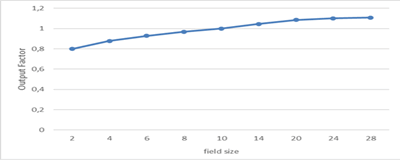
Output factors: Relative photon output factors showed little fluctuation as setup conditions for small fields were adjusted. Figure 1 displays the plotting of output factors for different field sizes. We compared the TPS (Treatment Planning System) data with the measured data we had gathered. The percentage disparities between the measured values and the TPS values for different field sizes are shown in the . The precision and consistency of the system's operation are shown by this analysis, which aids in locating any disparities and improving treatment planning techniques.
Fig.1. The plotting of output factors for different field sizes.
| Difference % Beam configuration: Mesures vs. TPS | |||||||||
|---|---|---|---|---|---|---|---|---|---|
| 2 | 4 | 6 | 8 | 10 | 14 | 20 | 24 | 28 | |
| 2 | -0,525 | -0,863 | -0,939 | -0,675 | -0,781 | -0,763 | -0,871 | -0,863 | -0,863 |
| 4 | -0,375 | -0,190 | -0,218 | -0,241 | -0,307 | -0,296 | -0,375 | -0,421 | -0,361 |
| 6 | -0,454 | 0,065 | -0,097 | -0,034 | -0,161 | -0,227 | -0,102 | -0,162 | -0,148 |
| 8 | -0,431 | 0,351 | 0,086 | 0,009 | -0,059 | -0,028 | -0,107 | -0,082 | -0,181 |
| 10 | -0,419 | 0,387 | 0,180 | 0,056 | 0,000 | -0,098 | -0,888 | -0,110 | -0,180 |
| 14 | -0,640 | 0,452 | 0,138 | 0,057 | 0,028 | 0,050 | -0,098 | -0,022 | -0,156 |
| 20 | -0,627 | 0,475 | 0,231 | 0,019 | 0,003 | -0,057 | -0,085 | -0,129 | -0,079 |
| 24 | -0,390 | 0,381 | 0,127 | 0,044 | 0,028 | 0,019 | -0,037 | -0,147 | -0,072 |
| 28 | -0,390 | 0,456 | 0,154 | 0,197 | 0,108 | -0,076 | -0,092 | -0,123 | -0,342 |
Tab. 1. Difference % Beam configuration: Mesures vs. TPS.
Relative dosimetry
• Energy stability check (TPR20/10): A water tank (blue phantom) was used for the energy check. With a standard deviation 0.0002, the Table 2 displays the consistency of TPR20/10 values obtained at various times during the day.
• Dose reproducibility: This is a quality control test for radiation dose uniformity with a 6FFF beam. To guarantee exact alignment, measurements are made at 100 cm SSD with an ionization chamber that is securely suspended. Consistency in probe distance is crucial for accurate results, and the configuration permits testing without going into the treatment room. The test shows good repeatability with variances well below the ± 1% specification, evaluating a range of MU values (500, 1000, and 1500) and with different gantry angles as shown in Tables 3 and 4.
| Energy | Time of measurement | TPR 20/10 | Difference % | Average | Standard deviation |
|---|---|---|---|---|---|
| 6FFF | 10:00 AM | 0,628 | Ref | 0,627875 | 0,000262996 |
| 12:00 AM | 0,6275 | 0.05 | |||
| 4:00 PM | 0,6281 | 0.01 | |||
| 6:00 PM | 0,6279 | 0.01 |
Tab. 2. The consistency of TPR20/10.
| Energy | Mu | 1 | 2 | Average | Deviation |
|---|---|---|---|---|---|
| 6FFF | 500 | 128,69 | 128,65 | 128,67 | 0,03% |
| 1000 | 257,51 | 257,5 | 2,57,505 | 0,00% | |
| 1500 | 386,18 | 386,14 | 386,16 | 0,01% |
Tab. 3. The dose reproducibility for different MUs.
| Energy | Mu | Intgration | Gantry angle | Deviation | |||
|---|---|---|---|---|---|---|---|
| 90° | 270° | 0° | 90° | 270° | |||
| 6FFF | 1000 | 1 | 257,73 | 258,92 | 257,51 | 0,09% | 0,55% |
| 1000 | 2 | 257,74 | 258,9 | 257,5 | |||
Tab. 4. NIO perceptions about the Blocks (B) and Dimensions (D) among different groups of professions.
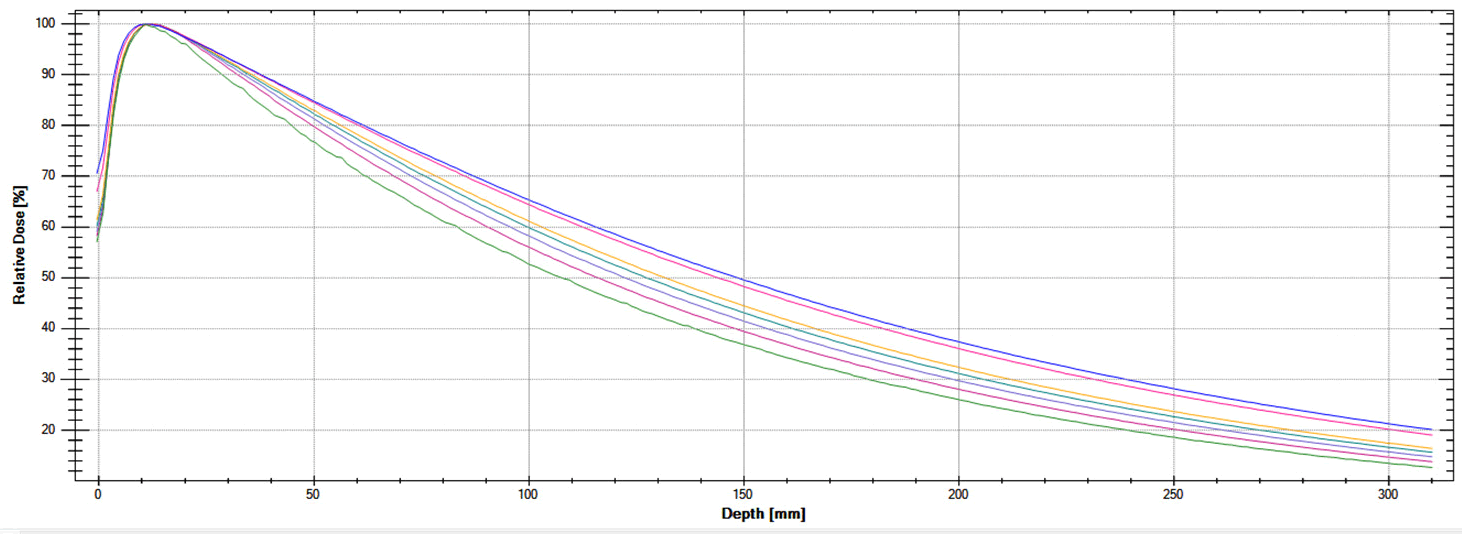
• Depth dose curves and profiles: Dmax is found nearer the surface for the flattening filter-free beams than for the flattened beams. For a range of field sizes, the central axis depth dose curves for the Halcyon 6 MV-FFF beam were measured. The plot of relative dose against field sizes, which range from 2 × 2 to 28 × 28 cm2, is shown in Figure 2. For the Halcyon 6 MVFFF beam, the measured dmax value was 1.3 cm. The surface is about 2 mm closer to this than it is to 6 MV unflattened beams.
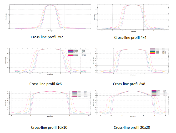
• Unflattened beam profiles slowly decrease toward the field edge after reaching their maximum dose on the center axis. As beam energy and field size increase, this effect becomes more noticeable. We have measured the diagonal and cross-line profiles for the Halcyon machine's 6 MF-FFF beams. Figure 3 displays the plotted profiles at different field sizes and depths. With Halcyon FFF beams, profile changes with depth were less pronounced. A number of factors, including penumbra and symmetry, were assessed for both small and large field sizes.
• The symmetry and penumbra for field sizes of 2 × 2, 6 × 6, 10 × 10, 20 × 20, and 28 × 28 cm² in cross-line geometry at 1,3 cm depth is summarized in Table 5. According to the table, compared to other conventional Clinac machines that currently exist and have the same 6 MV-FFF energy, the penumbra for Halcyon is sharper for the cross-line plane [5]. It was found that the penumbra slightly widened as the field area increased. The variation in the penumbra value is caused by the positioning of the jaws at various levels within the linear accelerator head.
| Photon beam energy | Field size | Symmetry % | Penumbre mm |
|---|---|---|---|
| 6FFF | 2 x 2 | 0,91 | 4,1|4,0 |
| 6 x6 | 0,23 | 5,3|5,3 | |
| 10 x 10 | 0,2 | 5,6|5,5 | |
| 20 x 20 | 0,37 | 5,9|6,0 | |
| 28 x 28 | 0,43 | 6,7|6,5 |
Tab. 5. The symmetry and penumbra various field sizes.
Fig.2. The plot PDD against field sizes.
Fig.3. The plot PDD against field sizes.
MLC tests
• Transmission measurements: An IBA Farmer ionization chamber in a water tank is used for the MLC transmission measurements. The average transmission for a 10 × 10 cm² field with a 6 MV FFF beam is 0.0944, which yields a transmission factor of 0.47106%. In radiotherapy, this guarantees precise dose administration. Figure 4 shown the plot of DLG values.
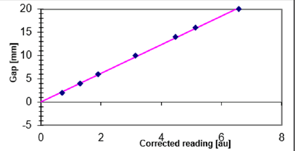
Fig.4. Plotted measurements of DLG.
• Dynamic Leaf Gap (DLG): Transmission measurements are used to determine the Dosimetric Leaf Gap (DLG). For various gap values, adjusted measurements are computed, with an average transmission of 0.0944. After using a linear fit, the DLG comes out to be -0.068, which is an extremely respectable value. This guarantees exact dose predictions in radiotherapy by accurately simulating the MLC.
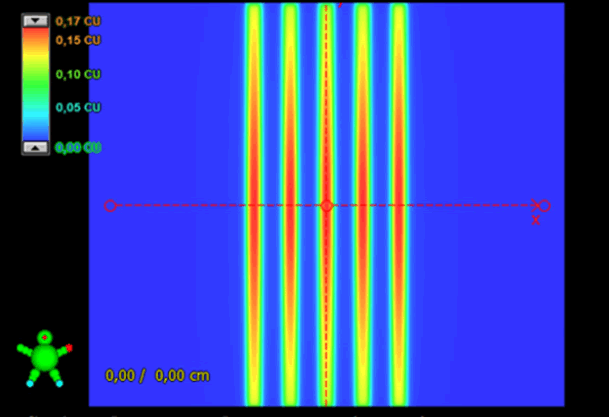
• Picket fence: 100 MU was delivered at a dose rate of 600 MU/ min for a static picket fence. Fences were shaped with a 1 cm slit aperture, five pickets total and a 1.5 cm space between them. Intentional errors were also introduced and assessed. Figure 5 showed each of the relevant fence images. Distal leaves (proximal leaves retracted) were responsible for shaping. In the middle of the field, between ×=-5.5 cm and ×=5.5 cm, fences were on display. The acquired Picket Fence images were analyzed using a gamma index evaluation utilizing Matrixx Resolution (IBA dosimetry).
The Figure 6 provided a summary of the results. It was evident from the figure that the readings were much below their tolerance limit.
Fig.5. Picket fence image.
Fig.6. Analysed image of picket fence using Gamma index.
Discussion
The Halcyon linear accelerator commissioning experience is summed up in this paper. Dosimetric, radiation safety and MLC parameters were all evaluated. The parameters that were obtained fell considerably short of the tolerance limits that were provided.
Additionally, the results showed great agreement with published data [12,13] and the other Halcyon machine. Radiation leakage and secondary malignancies were drastically reduced, according to MLC transmission and DLG values [8,14]. The Halcyon's new generation MLCs are to blame for this decrease. The precision of therapy delivery and the standard of care are increased by the latest generation of high-speed MLCs and upgraded imaging systems. On a daily basis, MV and KV images are used to confirm the patient's positional correctness on the therapy couch. Accurate placement of a water tank, solid water phantoms, detectors and patients relies on the Halcyon couch primarily on the obtained MV and KV images when there is no light field, optical distance indicator or mechanical distance measuring devices, which are present and used in Clinac series linear accelerators.
Megavoltage (MV) and Kilovoltage (KV) imaging systems with sophisticated iCBCT are available with Halcyon 4.0, which reduces noise in images and offers improved ability to see soft tissues. As is customary, the KV imager in Halcyon4.0 is placed perpendicular to the axis of the therapy beam. The field size of Halcyon's CBCT is limited to 28 cm in length and 50 cm in Field of View (FOV). The Halcyon4.0 linear accelerator's commissioning poses new difficulties because of its entirely novel setup geometry, lack of a light field and mechanical distance measuring equipment. The water phantom and additional dosimetry apparatus were positioned on the couch top using a novel technique.
A typical beam model is preloaded into the Halcyon Eclipse treatment planning system. PDD curves, central axis beam profiles and output factors are among the beam data that Varian provides. There were no significant differences between the measured and representative beam data sets that Varian submitted, according to our analysis. Additionally, we contrasted it with the commissioning data sets from Halcyon at the other institute. Both of them were found to be in good accord. The beam data model cannot be edited, modified or adjusted by the user using in relation to the measured data collection. The user must adjust the Halcyon machine to operate in accordance with TPS data rather than modifying the Eclipse beam data library. Medical physicists now have a new perspective on how to handle acceptance testing, commissioning and daily quality assurance of next-generation medical linear accelerators thanks to the preconfigured systems.
Conclusion
Halcyon's 6MV-FFF beams, radiation safety, dosimetrical and multi-leaf collimator parameters were all methodically measured. Beam profiles, relative output factors, the central axis depth dose curve and other dosimetric data were all thoroughly examined. Consistency and good agreement with other units of the same energy are demonstrated by the measured commissioning data. We received trustworthy assessments and insightful information on the features of the next-generation treatment delivery system from the commissioning data. For future reference, the methodically measured data may be helpful.
References
- Tsiamas P, Seco J, Han Z, Bhagwat M, Maddox J, et al. A modification of flattening filter free linac for IMRT. Med Phys. 2011; 38:2342-2352.
[Crossref] [Google Scholar] [PubMed]
- Feng Z, Yue H, Zhang Y, Wu H, Cheng J, et al. Monte Carlo simulation of beam characteristics from small fields based on True- Beam flattening-filter-free mode. Radiat Oncol. 2016; 11:30.
[Crossref] [Google Scholar] [PubMed]
- Halcyon Instruction for use. Varian Medical systems. Palo Alto, 2018.
- Ding GX, Munro P. Radiation exposure to patients from image guidance procedures and techniques to reduce the imaging dose. Radiother Oncol. 2013; 108:91-98.
[Crossref] [Google Scholar] [PubMed]
- Glideâ?Hurst C, Bellon M, Foster R, Altunbas C, Speiser M, et al. Commissioning of the Varian TrueBeam linear accelerator: A multi- institutional study. Med Phys. 2013; 40:031719.
[Crossref] [Google Scholar] [PubMed]
- Lloyd SA, Lim TY, Fave X, Floresâ?Martinez E, Atwood TF, et al. TG-51 reference dosim- etry for the Halcyon™: A clinical experience. J Appl Clin Med Phys. 2018; 19:98-102.
[Crossref] [Google Scholar] [PubMed]
- Richart J, Pujades MC, Perez-Calatayud J, Granero D, Ballester F, et al. QA of dy- namic MLC based on EPID portal dosimetry. Phys Med. 2012; 28:262-268.
[Crossref] [Google Scholar] [PubMed]
- Pathak P, Vashisht S. A quantitative analysis of intensity-modulated radiation therapy plans and comparison of homogeneity indices for the treatment of gynaecological cancers. J Med Phys. 2013; 38:67-73.
[Crossref] [Google Scholar] [PubMed]
- Musolino S. Absorbed Dose Determination in External Beam Radiotherapy: An International Code of Practice for Dosimetry Based on Standards of Absorbed Dose to Water Technical Reports Series No. 398. Health Physics. 2001; 81:592-593.
- Almond PR, Biggs PJ, Coursey BM, Hanson WF, Huq MS, et al. AAPM's TGâ?51 protocol for clinical reference dosimetry of highâ?energy photon and electron beams. Med Phy. 1999; 26:1847-1870.
- A modification of flattening filter free linac for IMRT
- Netherton T, Li Y, Gao S, Klopp A, Balter P, et al. Experience in commission- ing the halcyon linac. Med Phys. 2019; 46:4304-4313.
[Crossref] [Google Scholar] [PubMed]
- Gao S, Netherton T, Chetvertkov MA, Li Y, Court LE, et al. Acceptance and verification of the Halcyon Eclipse linear accelerator treatment planning system without 3D water scanning system. J Appl Clin Med Phys. 2019; 20:111-117.
[Crossref] [Google Scholar] [PubMed]
- Thomas L, Chen C. Physical and dosimetric aspects of multileaf collimation system used in dynamic mode for implementing intensity modulated radiotherapy. AAPM. 1998.
[Crossref] [Google Scholar] [PubMed]
