Research Article - Onkologia i Radioterapia ( 2020) Volume 14, Issue 4
In vivo dosimetry evaluation of semiconductor diodes and Thermoluminscence Detectors (TLDS) in advanced radiotherapy techniques
Areej Akram Al-Taee1,2*, Wieeam Abdul-Fattah Saleh3 and Magdy M. Khalil22Oncology Teaching Hospital, Medical City Complex, Baghdad, Iraq
3Department of Physics, Helwan University, Cairo, Egypt
Areej Akram Al-Taee, Baghdad Radiotherapy and Nuclear Medicine Centre, Medical City Complex, 10001,Baghdad, Iraq, Tel: 9647733962400, Email: za4389452@gmail.com
Received: 03-Aug-2020 Accepted: 22-Aug-2020 Published: 31-Aug-2020
Abstract
The performing of IVD for Intensity Modulated Radiotherapy (IMRT) and Volumetric Modulated Arc Therapy (VMAT) is not well established and the studies and trails available are not sufficient to give us a clear view of the verified IVD methods in modulated radiotherapy. The objective of this study was to give validation of using diodes and TLDs for in vivo dosimetry in advanced radiotherapy techniques for early detection the uncertainties and significant errors of the dose delivery. Thirty nine patients (23 female and 16 male) with different clinical sites were selected for this study. The period of the study last for five months at Children's Cancer Hospital 57357 and we used paediatric anthropomorphic A 10-years-old phantom to measure doses in IMRT and VMAT by using Thermoluminescent Dosimeters (TLDs) and semiconductor diodes. Also, we utilized the Treatment Planning System (TPS) to calculate doses and compared it with detector readings. Diode is good to be used in IMRT but avoiding total blocked and partial blocked region of MLC that effective on measured diode ± 6 %. Diode is not valid to be used in VMAT cased orientate and dynamic MLC. Result of measurement with TLD in IMRT is less in accuracy than that for VMAT distribution at the edges. The penumbra edges have a percentage difference of ±10 % while it is very close to zero at the middle region. We have evaluated the use of diodes and TLD for application to IMRT and VMAT in vivo dosimetry. Phantom measurements in which diode and TLD used were compared, showing them to be in agreement to generally better than 90%. In comparison with plan prediction of TPS doses, average percent differences in the phantom measurements and patients also were mostly within 35%, with some discrepancies.
Keywords
In vivo dosimetry, IMRT QA, dose verification on VMAT, diode dosimetry, TLD dosimetry
Introduction
The purpose of radiotherapy is to securely, precisely, and efficiently deliver radiation to treat several types of malignant and benign tumour. Recently, a number of radiation events in various countries have been reported [1], plus suboptimal patient treatments may also occur because one or more of the parameters involved in a patient irradiation may have a systematic error [2]. The International Commission of Radiological Units (ICRU) sets a tolerance of ± 5 % on dose delivery, with more recent data limiting the overall tolerances to ± 3 %. One of the best methods for accurate dose delivery and superiority check is in vivo dosimetry, while radiotherapy IAEA is achieved to set the action level the same as the tolerance level (5%) [3]. The amount of light output is relative to the dose received by the crystal. For many years, TLDs were the only option for any practical in vivo dose measurement However, a major drawback associated with these dosimeters is the requirement for postirradiation processing by heating the sample and measuring the light output from it to determine the dose received. This means “real-time” dose measurement is impossible and is a major reason why TLDs began to be replaced by diodes While TLDs are still in use in skin dose detection [4]. Kinhikar et al. stated validated of using diode in Intensity-Modulated Radiotherapy (IMRT) they used x-ray beam from energy of 6 MV and 15 MV. 10 × 10 cm2 field size, at a Target-To-Surface Distance (TSD) of 95 cm and 5 cm depth in water [5]. Morin, et al. compared two Plastic Scintillation Detectors (PSDs) to several commercial stereotactic dosimeters by measuring total scatter factors and dose profiles on a Cyber Knife system [6]. Two PSDs were develop having sensitive volumes of 0.196 and 0.785 mm and compared with other detectors [6]. Dipasquale et al. estimated the In-Vivo Dosimetry (IVD) distribution using Cone-Beam Computed Tomography Scans (CBCTs) and Thermoluminescent Dosimeters (TLDs) in 11 patients with anal or rectal cancer treated with Volumetric Modulated Arc Therapy (VMAT) [7]. Gee et al. estimated the resulting dose reduction in vivo, compared with Treatment Planning System (TPS) by using sixteen patients receiving Post-Mastectomy Radiotherapy (PMRT) had in vivo dosimetry prospectively executed with ethics board approval. Port was located within the expanded chest wall using the planning CT scan [8]. Maulana et al. verified the dose in IMRT and VMAT technique in prostate cancer cases correspond to TPS dose using phantom base on ICRU No.50. The dose verification of the target and Organ At Risk (OAR) was implement by placing the TLD [9]. People, investigated the various gantry angle and SSD dependencies of TLD and MOSFET dosimeters [10]. LiF (Mg) TLD and MOSFET were used in this study. Dosimeter systems were calibrated and then irradiated at various gantry angle and SSD by applying 6 MV photon energy [10].
Materials and Methods
Study design
Participants: Thirty-nine (27 females and 12 males) patients with different region were select for this study. Doing plans were for each patient. These treatment plans were matching with using advance techniques IMRT and VMAT. The beam angle was choosing to minimize doses to the critical organs and to achieve high dose fall-off around the target at the same time (Figure 1).
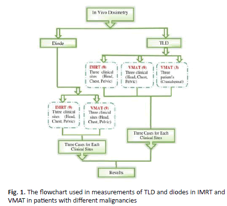
Figure 1. The flowchart used in measurements of TLD and diodes in IMRT and VMAT in patients with different malignancies
Irradiation facilities: A Linear Accelerator 6 MV generated by two matched Elekta Versa HD utilize. A 10-years-old paediatric Cecil phantom, 81.5 cm tall and 32 kg weight was used. CT simulation imaging prior to radiation delivery is used. Thermoluminescent Detectors (TLD´s) products used in radiation dosimetry. The P-type semiconductor diode (Model IBA dosimetry EDP-10270 Green) has been used. Radiotherapy plans will be calculated by using Monaco 5.11, Elekta.
Diode calibration: The initial diode calibration was carried out in a 10 × 10 cm2 field at 100 cm filed size using a phantom of substitute slabs. The diode was calibrated with 6 MV photons for 10 × 10 cm2 at 100 cm SSD. Then applied the diode at Cecil phantom and patients for three clinical regions (head, chest, and pelvic). All measured doses were compared to the Treatment Planning System (TPS) dose with IMRT and VMAT which were performed using an Elekta Versa HD. The primary objective for each plan was to 95% of Planning Target Volume (PTV) covered by 95% of the prescribed dose while minimizing the dose to the Organ At Risk (OARs) were avoided as much as possible by selecting the optimal table positions. Planning head cases on patients prescribed dose 5400 cGy/30 fractions number of fields 6 start from beams angle (0°, 70°, 140°, 210°, 280° and 340°). Planning chest cases on patient prescribed dose 1200 cGy/8 fractions number of fields 6 start from beams angle (11º, 230º, 260º, 290º, 320º and 350º). Planning pelvic cases on patient prescription dose 5940 cGy/33 fraction number of fields 6 start from beams angle (0º, 70º, 210º, 280º, 340º and 260º).
TLD dosimeters for pediatric phantom and patients in IMRT and VMAT
For making planning for patients, the primary objective for each plan was to 95% of Planning Target Volume (PTV) covered by 95% of the prescribed dose while minimizing the dose to the Organ At Risk (OARs) were avoided as much as possible by selecting the optimal table positions, Arc angles and the most fitted cone size. Similar concept for IMRT choosing beam angle that avoiding OARs. The mean planning target volume and compare dose at same depth by using diode. Peripheral dose measurements were taken in paediatric phantom and patients by using TLDs (7-LiF: Mg, Cu.P), All TLDs crystals was making validation for them. The whole set of TLDs was irradiated with a known dose using (10 cm × 10 cm) 6MV X-ray beam of a linear accelerator ELEKTA. Used TLD to obtained measurements in IMRT and VMAT. After doing plan for head case in IMRT and in VMAT for phantom and measured dose in the centre of beam for three points and take average. Putting three-TLD crystal on the phantom and take session. Then annealing TLD at 240°C for 10 mint and take average measured to multiplying by calibration factor.
TLD in IMRT
Performed plan for the patient by different angle beams and number of segmentations, as far as shape and size and locations of tumours and take three sits (head, chest, and pelvic). We put Three TLD crystals for each angle and aligned parallel one line then warped to expose for radiation and take it to laboratory for heating all crystals matching doses that obtained it from TLD with doses from TPS Figure 2A.
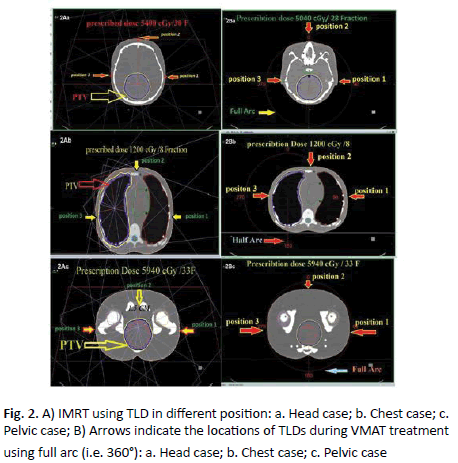
Figure 2. A) IMRT using TLD in different position: a. Head case; b. Chest case; c. Pelvic case; B) Arrows indicate the locations of TLDs during VMAT treatment using full arc (i.e. 360°): a. Head case; b. Chest case; c. Pelvic case
TLD in VMAT Arc
Preformed plan for paediatric patients by full or half arc and calculate doses in the angle (90°, 0°, and 270°) and putting Three TLD crystals for each angle then measured them after exposure to radiation and matching it with TPS. Head tumour prescribed dose 5040 cGy/28 Fractions measured dose by TPS at (0°, 90°, 270°) angle. Then when patient take his fraction of Radiation Therapy (RT) we put three TLD crystals for each angle and aligned parallel one line then warped to exposed for radiation and take it for same process doing for chest and pelvic but different angle beam and doses (Figure 2B). Taking all TLD crystals after treatment and annealing it to matching doses that obtained it from TLD with doses from TPS.
Quantitative assessment of dosimeter performance with respect to TPS was calculated using the formula:
%Deviation=(Dosimeter reading-TPS)/TPS × 100
Values of positive and negative sign indicate an overestimate and underestimate of the dosimeter respectively (e.g. TLD or diodes) with respect to TPS calculations.
Results
IMRT plans for Cecil phantom study
Real-time IMRT plans dosimeters measurements using diode on Cecil phantom are described in (Table 1), which contains the measurements performed for three clinical sites (head, chest, pelvis) the mean ratio of diode doses between data measured and calculated for the IMRT. As shown in (Figure 3) the deviation between measured and calculated dose by TPS in case of head region was 3.97% for the two angles 280° and 340°.
| Phantom | Clinical Sites | Angle beam | Average dose diode | Average dose three points (TPS) | Deviation % (diode.-TPS/TPS) |
|---|---|---|---|---|---|
| Head | 280° | 29 | 28.5 | +1.75 | |
| 340° | 24 | 22.6 | +6.19 | ||
| Average Deviation=+3.97% | |||||
| Chest | 11° | 7.3 | 7.7 | -5.19 | |
| 320° | 33.4 | 29.6 | +0.12 | ||
| Average Deviation= ± 2.65 % | |||||
| Pelvic | 30° | 22.3 | 22 | +1.36 | |
| 80° | 42 | 45 | -6.66 | ||
Average Deviation= ± 4.01 %
Table 1. Dosimetry evaluation for three clinical sites (i.e. head-chest-pelvic) performed on Cecil phantom measured by semiconductor diode in IMRT
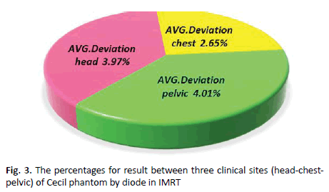
Figure 3. The percentages for result between three clinical sites (head-chestpelvic) of Cecil phantom by diode in IMRT
It was shown that the average deviation for chest was 2.65% for angle 11° and 320°. In pelvic region, average deviation measurement was 4.01% for the two angles 30° and 80°. Observed average deviation for pelvis was higher than other sites as it contains steep dose gradients and thus small deviations in position may cause larger deviations in dose.
In vivo dosimetry for IMRT plans using diodes
In IMRT diode, nine patients with different clinical sites (head, chest, and pelvic) applying different angles and doses were carried out. Diode measurements was performed twice on different days to investigate the reproducibility of diode response.
Diode in IMRT for head
Three patients with head tumour had undergone IMRT planning by TPS and calculated dose at centre of beam for each angle. Patient measurements were performed three times at maximum.
In case of treated brain tumours, the first patient at gantry angle beam 0o, the observed percentage deviation between diode and calculated value was 0.0%, (Table 2 and Figure 4A).
| Number of patients | Beam Angle | First diode cGy | Second diode cGy | Average value | TPS | deviation % (Diode-TPS)/TPS | Total MU | Total Number of Segments | Open Segments | Blocked Segments | Partially Blocked Segments | |||
|---|---|---|---|---|---|---|---|---|---|---|---|---|---|---|
| No. | MU | No. | MU | No. | MU | |||||||||
| Patient 1 | 0 | 21 | 21 | 21 | 21 | 0 | 38.03 | 4 | 2 | 24.65 | 1 | 5.65 | 1 | 7.73 |
| 2800 | 29 | 28.5 | 28.7 | 28.5 | 0.8 | 41.11 | 5 | 2 | 25.19 | 2 | 9.02 | 1 | 6.89 | |
| Average Deviation Patient #1=+0.43% | ||||||||||||||
| Patient 1 | 700 | 23 | 24 | 23.5 | 22.9 | 2.6 | 35.46 | 3 | 2 | 23.96 | . | . | 1 | 11.5 |
| 3400 | 24 | 24 | 24 | 22.6 | 6.1 | 42.63 | 4 | 2 | 34.55 | . | . | 1 | 8.08 | |
| Average Deviation Patient #2=+ 4.40% | ||||||||||||||
| Patient#3 | 1400 | 27 | 27 | 27 | 27 | 0 | 33.55 | 5 | 4 | 29.17 | . | . | 1 | 4.38 |
| 2800 | 28.8 | 28.7 | 28.7 | 28.5 | 0.7 | 53.87 | 6 | 3 | 37.61 | 2 | 10.24 | 1 | 6.03 | |
Average Deviation patient #3=+0.35%
Average Deviation for Head=+5.18 %
Table 2. Dosimetry evaluation for three cases of head tumour performed on paediatric patients measured by semiconductor diode in IMRT
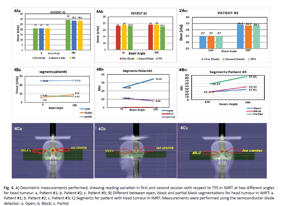
Figure 4. A) Dosimetric measurements performed, showing reading variation in first and second session with respect to TPS in IMRT at two different angles for head tumour: a. Patient #1; b. Patient #2; c. Patient #3; B) Different between open, block and partial block segmentations for head tumour in IMRT: a. Patient #1; b. Patient #2; c. Patient #3; C) Segments for patient with head tumour in IMRT. Measurements were performed using the semiconductor diode detector: a. Open; b. Block; c. Partial
In addition, at gantry angle 280° the percentage deviation was 0.8%. In second patient at gantry angle 70°, percentage deviation was 2.6%. At gantry angle 340° percentage deviation was 6.1%. In the third patient, gantry angle 1400 the percentage deviation was zero, at gantry angle of 280° the percentage deviation was 0.7%, (Figure 4B). More analysis was performed on the three patient plans. The treatment fields on these plans (n=6) were analysed segment by segment in case of blocked, not-blocked, and partially blocked. The resulting percentage deviation values represent the percentage of the MUs delivered to the diode via blocked, partially blocked, or not blocked segments (Figure 4C).
Diode in IMRT for chest
Three patients with chest mass were then selected and IMRT planning was performed. The patient measurements were performed three times at maximum. The result of chest from diode in IMRT is explained in (Table 3).
| CHEST IMRT PLAN | Number of Patient | Beam Angle | First diode cGy | second diode cGy | Average value | TPS | Deviation % (Diode-TPS) /TPS | Total MU | Total Number of Segments | Open Segments | Blocked Segments | Partially Blocked Segments |
|||
|---|---|---|---|---|---|---|---|---|---|---|---|---|---|---|---|
| No. | MU | No. | MU | No. | MU | ||||||||||
| Patient #1 | 0 | 29.7 | 29.7 | 29.7 | 30 | -1 | 62.9 | 9 | 6 | 45.89 | 1 | 5.09 | 2 | 11.91 | |
| 200 | 109 | 109 | 109 | 107.4 | 1.4 | 61.6 | 8 | 5 | 45.14 | 2 | 9.55 | 1 | 6.93 | ||
| Average Deviation Patient#1 = ± 1.24% | |||||||||||||||
| Patient #2 | 1300 | 10.2 | 10 | 10.1 | 9.2 | 9.7 | 56.3 | 7 | 4 | 37.4 | 3 | 18.9 | . | . | |
| 3100 | 22 | 22.3 | 22.1 | 19 | 16 | 38.7 | 5 | 2 | 19.94 | 2 | 12.58 | 1 | 7.2 | ||
| Average Deviation Patient#2=+12.5% | |||||||||||||||
| Patient #3 | 2600 | 7 | 7.3 | 7.1 | 7.7 | -7.7 | 54.1 | 9 | 5 | 38.04 | 1 | 4 | 3 | 12.11 | |
| 110 | 49 | 51.4 | 50.2 | 50.7 | -0.9 | 60.3 | 8 | 4 | 39.39 | 2 | 11.48 | 2 | 9.5 | ||
Average Deviation Patient#3= -3.35%
Average Deviation for Chest = ± 5.69%
Table 3. Dosimetry evaluation for three cases of chest cancer performed on paediatric patients measured by semiconductor diode in IMRT
In the first patient, the gantry angle beam 0o had nine segments MU variation in the range of 45.89, 5.09, and 11.91 MU with percentage deviation between diode and TPS of 1% whereas in gantry angle 20o the percentage deviation was 1.4%. In the second patient, we noticed at gantry angle 130° the percentage deviation was 9.7% whereas in gantry angle 310° the percentage deviation was 16.0%. In the third patient at beam angle of 260°, the percentage deviation was 7.7% while at beam angle of 11° the percentage deviation was 0.9% (Figure 5A). Diode response variation with the number of segments that cover the diode with not blocked, blocked, and partially blocked are shown in (Figure 5B). The plans with MLCs moved to completely block the diode (patient#2) two blocked segments. This effect of dose variation especially patient #2 at beam angle 3100 where the correlation between partial blockage and diode response was evident. Although the percentage difference between measured and calculated values were generally within 2% (Figure 5C).
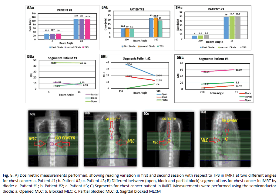
Figure 5. A) Dosimetric measurements performed, showing reading variation in first and second session with respect to TPS in IMRT at two different angles for chest cancer: a. Patient #1; b. Patient #2; c. Patient #3; B) Different between (open, block and partial block) segmentations for chest cancer in IMRT by diode: a. Patient #1; b. Patient #2; c. Patient #3; C) Segments for chest cancer patient in IMRT. Measurements were performed using the semiconductor diode: a. Opened MLC; b. Blocked MLC; c. Partial blocked MLC; d. Sagittal blocked MLCM
Diode in pelvic
The first patient of the pelvic region group demonstrated that at gantry angle 0° a percentage deviation between diode and TPS was 2.63% (Table 4).
| PELVIC IMRTÂ PLAN | case | Beam Angle | first diode cGy | second diode cGy | Average value | TPS | Deviation % (Diode-TPS)/TPS | Total MUs’ | Total Number of Segments | Open Segments | Blocked Segments | Partially Blocked | |||
|---|---|---|---|---|---|---|---|---|---|---|---|---|---|---|---|
| No. | MU | No. | MU | No. | MU | ||||||||||
| 1 | 0 | 39 | 35 | 37 | 38 | -2.63 | 80.6 | 7 | 3 | 44.1 | 2 | 13.82 | 2 | 22.77 | |
| 700 | 37 | 35 | 36 | 34 | 5.8 | 73.1 | 6 | 3 | 49.35 | 2 | 13.25 | 1 | 10.51 | ||
| Average Deviation Patient#1= ± 4.25% | |||||||||||||||
| 2 | 300 | 45.5 | 45 | 45.5 | 45.7 | -0.43 | 50.3 | 5 | 2 | 26.25 | 1 | 6.16 | 2 | 17.92 | |
| 3400 | 42 | 42 | 42 | 45 | -6.66 | 52.3 | 8 | 3 | 24.6 | 4 | 21.35 | 1 | 6.35 | ||
| Average Deviation Patient#2= -3.11% | |||||||||||||||
| 3 | 3000 | 42 | 42 | 42 | 45 | -6.66 | 54.1 | 9 | 5 | 38.04 | 1 | 4 | 3 | 12.11 | |
| 2900 | 50 | 61 | 55.8 | 58.7 | 4.85 | 60.3 | 8 | 4 | 39.39 | 2 | 11.48 | 2 | 9.5 | ||
Average Deviation Patient#3= ± 5.75%
Table 4. A) Dosimetric measurements performed, showing reading variation in first and second session with respect to TPS in IMRT at two different angles for head tumour: a. Patient #1; b. Patient #2; c. Patient #3; B) Different between open, block and partial block segmentations for head tumour in IMRT: a. Patient #1; b. Patient #2; c. Patient #3; C) Segments for patient with head tumour in IMRT. Measurements were performed using the semiconductor diode detector: a. Open; b. Block; c. Partial
In addition, gantry angle 70° the percentage deviation was 5.88%. In the second patient at gantry angle 30°, the percentage deviation was 0.43% and beam angle of 340° the percentage deviation was 6.66%. In the third patient at gantry angle 30°, the percentage deviation was 6.66%, whereas at gantry angle 290° the percentage deviation was 4.85 % as demonstrated in (Figure 6A). Diode readings are subject to more uncertainty, generally exhibiting greater over response, when exposed partially to segments as opposed to exposed fully or not at all. This is similar to the observation in chest plans with segments partially blocking the diode seen in (Figure 6B). One trend observed, however, was that the diode response consistently, but slowly, increased with increasing target size, although the percentage difference between measured and calculated values were generally within 2% patient #3 angle 290o. Plans with larger target sizes a contained, in general, larger segments. Thus, as the target size increased in dimension, resulting in increased segment size, the magnitude of the response of the diode increased. The percentage difference of diode to calculated readings meaning that for smaller target sizes the measured value is less than calculated, whereas for the larger target sizes the measured value is more than calculated. This is probably due to increase in scatter dose reaching the diodes because of increase in segment sizes, (Figure 6C). The results of patient measurements demonstrated indicated an average difference of 1% with a standard deviation of 3%.
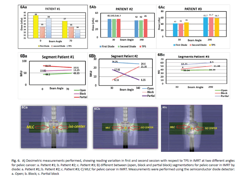
Figure 6. A) Dosimetric measurements performed, showing reading variation in first and second session with respect to TPS in IMRT at two different angles for pelvic cancer: a. Patient #1; b. Patient #2; c. Patient #3; B) different between (open, block and partial block) segmentations for pelvic cancer in IMRT by diode: a. Patient #1; b. Patient #2; c. Patient #3; C) MLC for pelvic cancer in IMRT. Measurements were performed using the semiconductor diode detector: a. Open; b. Block; c. Partial block
In vivo dosimetry for VMAT plans using diode for patients and Cecil phantom
The results of patients with different clinical sites performed planning by TPS, the percentage deviation between diode and TPS was more than 50%. In head different between TPS and diode was 40%, 55% in chest and 53% in pelvis. Diode-based point dose measurements are not appropriate for verification of dose delivered when treating with highly modulated, rotational or adaptive techniques (Table 5 and Figure 7).
| phantom | Number of patients | position of TLD | measured dose by three TLD cGy | measured does TPS average 3 point | Deviation% (TLD â??TPS/TPS) |
|---|---|---|---|---|---|
| 900 | 38.6 | 37 | 4.32 | ||
| HEAD | 0 | 26.8 | 26 | 3.07 | |
| 2700 | 46 | 45 | 2.22 | ||
| Average Deviation Head (3 Angles)=+3.20 % | |||||
| 900 | 19.2 | 19.9 | -3.51 | ||
| chest | 0 | 21.8 | 20.5 | 6.34 | |
| 2700 | 16.8 | 15.2 | 10.52 | ||
| Average Deviation Patient chest (3 Angles)= ± 6.79 % | |||||
| 900 | 35.6 | 37 | -3.78 | ||
| pelvic | 0 | 40.9 | 45.8 | -10.69 | |
| 2700 | 67 | 65 | 3.07 | ||
Average Deviation for pelvic (3 Angles)= ± 5.84%
Table 5. Dosimetry evaluation for three clinical sites (i.e. headâ?? chestâ??pelvic) performed on Cecil phantom measured by TLD in VMAT
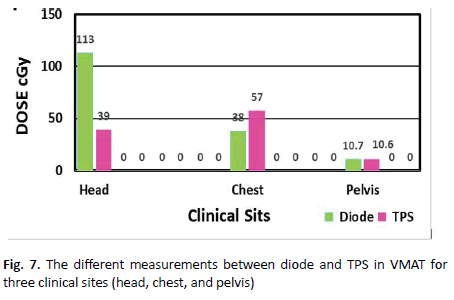
Figure 7. The different measurements between diode and TPS in VMAT for three clinical sites (head, chest, and pelvis)
VMAT plans for Cecil phantom study
TLD measurements on the phantom plans in VMAT were calculated by the treatment planning system contains the mean ratio of TLD doses between what was measured to what was calculated for the VMAT. These results for three deliveries separate sites are shown in (Figure 8). It was observed that the results performed for three angles of the head average deviation was 3.20% while average deviation for three angles of the chest was 6.79%. In the pelvic region the average deviation was 5.84%. Practical average deviation for the chest higher than other sites contain steep dose gradients and thus small deviations in position may cause larger deviations in the dose.
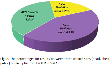
Figure 8. The percentages for results between three clinical sites (head, chest, pelvic) of Cecil phantom by TLD in VMAT
TLD in VMAT for head
The dose measurements of target for VMAT are shown in (Table 6). The table shows that the average deviation in the patient #1 was 1.98%, whereas the average deviation in the patient #2 was 21.20%, and the average deviation in the patient #3 was 2.11% (Figure 9A).
| Head VMATÂ Â PLAN | Number of Patient | Position of TLD | Average dose (TLD)cGy | Average dose (TPS) cGy | Deviation% (TLD-TPS/TPS) |
|---|---|---|---|---|---|
| 900 | 75.8 | 75 | 1.06 | ||
| Patient #1 | 0 | 29.1 | 30.6 | -4.9 | |
| 2700 | 42 | 42 | 0 | ||
| Average  Deviation Patient #1 (3 Angles)= ± 1.98 % | |||||
| 900 | 30.4 | 37 | -17.83 | ||
| Patient #2 | 0 | 10.6 | 15 | -29.33 | |
| 2700 | 72.2 | 62 | 16.45 | ||
| Average  Deviation Patient #2 (3 Angles)= ± 21.20 % | |||||
| 900 | 75.2 | 79.3 | -5.17 | ||
| Patient #3 | 0 | 10.7 | 10.6 | 0.94 | |
| 2700 | 85.6 | 85.8 | -0.23 | ||
Average Deviation Patient #3 (3 Angles)= ± 2.11 %
Average Deviation for head= ± 8.43 %
Table 6. Average dosimetry in VMAT by used Three TLD for each patient head tumour and three points in TPS
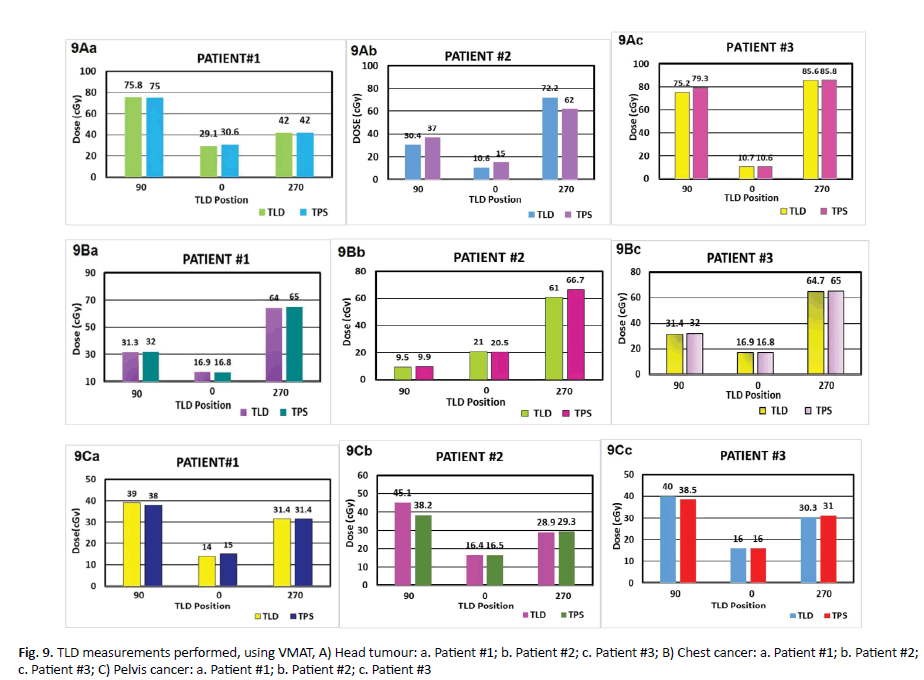
Figure 9. TLD measurements performed, using VMAT, A) Head tumour: a. Patient #1; b. Patient #2; c. Patient #3; B) Chest cancer: a. Patient #1; b. Patient #2; c. Patient #3; C) Pelvis cancer: a. Patient #1; b. Patient #2; c. Patient #3
TLD in VMAT for chest
The results of VMAT plan by TLD was explained in (Table 7). It shows the different between the measured dose by VMAT for three TLD and TPS for the average of three points. In the first patient the average of three crystals TLD at beam angle 90° was 31.3 cGy but in TPS was 32 cGy with a difference of 2.18% while at the angle 0° the dose measured by TLD was 16.9 cGy but with TPS was 16.8 cGy providing a percentage different of 1% whereas at the angle 270° the measured by TLD was 64 cGy but by TPS was 65 cGy yielding a percentage deviation of 2%. In the second patient the average of three TLD at beam angle 90° was 9.5 cGy but in TPS was 9.9cGy providing a percentage deviation of 4.04%. At angle 0° measurements of TLD was 21 cGy but by TPS was 20.5 cGy yielding percentage deviation of 2.43%. At angle 270° measured by TLD the dose was 61 cGy but by TPS was 66.7 cGy providing a percentage deviation of 8.54%. In the third patient, the average measurements of beam angle 90o by TLD was 31.4 cGy but 32 cGy by TPS providing a percentage deviation of 1.87%. At angle 0° measured by TLD was 16.9 cGy but by TPS was 16.8 cGy with a percentage deviation of 1%. At angle 270° TLD measurement was 64.7 cGy whereas TPS provided a value of 65 cGy yielding a percentage deviation of 0.46 % (Figure 9B).
| Chest VMATÂ Â Plan | Number of patients | Gantry angle of position TLD | Average dose by 3 TLD cGy | Average does TPS 3 POINT | Deviation% (TLD.TPS/TPS) |
|---|---|---|---|---|---|
| 900 | 31.3 | 32 | -2.18 | ||
| Patient#1 | 0 | 16.9 | 16.8 | 1 | |
| 2700 | 64 | 65 | -2 | ||
| Average Deviation Patient #1 (3 Angles)= ± 1.43 % | |||||
| 900 | 9.5 | 9.9 | -4.04 | ||
| Patient#2 | 0 | 21 | 20.5 | 2.43 | |
| 2700 | 61 | 66.7 | -8.54 | ||
| Average Deviation  Patient #2 (3 Angles)= ± 5 % | |||||
| 900 | 31.4 | 32 | -1.87 | ||
| Patient#3 | 0 | 16.9 | 16.8 | 1 | |
| 2700 | 64.7 | 65 | -0.46 | ||
Average  Deviation  Patient #3 (3 Angles) = ± 0.97 %
Average Deviation for chest= ± 2.46 %
Table 7. Average dosimetry of used Three TLD for each case VMAT chest tumour, compare it with three point in TPS, and take average for it Average dosimetry of used Three TLD for each case VMAT chest tumour, compare it with three point in TPS, and take average for it
TLD in VMAT for pelvic region
Results of TLD in VMAT are explained in Table 8. In the first patient, deviation of the TLD at beam angle 9° was 39 cGy but TPS was 38 cGy with standard deviation of 2.63%. At the angle 0° measurements by TLD was 14.0 cGy but 15 cGy by TPS yielding a percentage difference of 6.66%. At angle 270o TLD provided a dose of 31.4 cGy but by TPS a dose of 31.4 cGy with percentage deviation of zero. In the second patient the deviation of three TLD at the beam angle 90° by TLD was 45.1 cGy but TPS was 38.2 cGy with percentage deviation of 8.06%. At angle 0° measured by TLD the reading was 16.4 cGy but TPS was 16.5 cGy providing a percentage deviation of 0.60%. In angle 270° TLD measured was 28.9 cGy but by TPS was 29.3 cGy with percentage deviation of 1.36%. The results in the third patient for the average of three TLD at beam angle 90° was 40 cGy and 38.5 cGy by TLD and TPS respectively with a percentage deviation of 3.89%. At angle 0° measurements were exact in both TLD and TPS (16.0 cGy). Whereas at angle 270° TLD measured was 30.3 cGy but TPS was 31.0 cGy with percentage deviation of 2.25%, explain in the (Table 8 and Figure 9C).
| pelvic VMATÂ Â PLAN | Patients Numbers | Position of TLD | Average dose by Three TLD cGy | Average does TPS three Points | Â %Deviation TLD-TPS/TPS |
|---|---|---|---|---|---|
| 900 | 39 | 38 | 2.63 | ||
| Patient#1 | 0 | 14 | 15 | -6.66 | |
| 2700 | 31.4 | 31.4 | 0 | ||
| Average Deviation Patient #1 (3 Angles)= ± 3.09 % | |||||
| 900 | 45.1 | 38.2 | 18.06 | ||
| Patient#2 | 0 | 16.4 | 16.5 | -0.6 | |
| 2700 | 28.9 | 29.3 | -1.36 | ||
| Average Deviation Patient #2 (3 Angles)= ± 5.76 % | |||||
| 900 | 40 | 38.5 | 3.89 | ||
| Patient#3 | 0 | 16 | 16 | 0 | |
| 2700 | 30.3 | 31 | 2.25 | ||
Average Deviation Patient #3 (3 Angles)=+2.04 %
Average Deviation for Pelvic= ± 3.63 %
Table 8. Average dosimetry of used Three TLD for each case VMAT pelvic tumour, compare it with three point in TPS, and take average for it
TLD in IMRT for head
The result of using TLD in IMRT technique for head tumour are described in (Tables 9 and 10). In the first patient of brain tumour at beam angle 0° measured by TLD the reading was 40 cGy but 37.5 cGy using TPS approximately a percentage difference of 6.66%. Where as in the second beam at 280° measured by TLD, the reading was 28.5 cGy whereas a value of 29 cGy using TPS providing a percentage difference of 1.72%. The average deviation for patient #1 was 4.19%. In the second patient of head at beam angle 70° measured by TLD, the reading was 16 cGy whereas the TPS reading was 18 cGy, the percentage difference of 11.11%. At beam 340° measured TLD was submission 22.9 cGy 23 cGy by TLD and TPS respectively with percentage difference of 0.43%, seeing that the deviation difference for patient #2 was 5.77%. In the third patient of the head tumour at beam angle 140° measurement of TLD was 30.3 cGy but 27 cGy with TPS yielding a deviation of 12.22%. In the second beam at 280° measurement of TLD was |22.6 cGy but TPS provided a reading of 24 cGy with a percentage deviation of 5.83%. However, average deviation for patient #3 was 9.02%, display in (Figure 10A).
| Phantom | Clinical sites | Angle beam | Average dose TLD | Average dose three points (TPS) | Deviation% [TLD-TPS/TPS] |
|---|---|---|---|---|---|
| head | 2800 | 30.2 | 29 | 4.13 | |
| 3400 | 25.5 | 23.7 | 7.59 | ||
| Average Deviation head=+5.86 % | |||||
| chest | 110 | 7.7 | 7.4 | 4.05 | |
| 3200 | 33.4 | 30.6 | 9.15 | ||
| Average Deviation chest=+6.60 % | |||||
| Pelvic | 300 | 22.3 | 21.8 | -2.29 | |
| 800 | 42.9 | 45 | -4.66 | ||
Average Deviation pelvic= -3.47 %
Table 9. Dosimetry evaluation for three clinical sites, (head-chest-pelvic) on phantom in IMRT by TLD
| Head tumour | Number of cases | Angle of beam | Average dose three (TLD) | Average dose three points (TPS) | Deviation % (TLD-TPS/TPS) |
|---|---|---|---|---|---|
| Patient#1 | 0 | 40 | 37.5 | 6.66 | |
| 280 | 28.5 | 29 | -1.72 | ||
| Average Deviation patient #1= ± 4.19 % | |||||
| Patient#2 | 70 | 16 | 18 | -11.11 | |
| 340 | 22.9 | 23 | -0.43 | ||
| Average Deviation patient #2=Â ? 5.77 % | |||||
| Patient#3 | 140 | 30.3 | 27 | 12.22 | |
| 280 | 22.6 | 24 | -5.83 | ||
Average Deviation patient #3= ± 9.02 %
Average Deviation for three patients of head= ± 6.32 %
Table 10. Average dosimetry of used Three TLD for each case IMRT head tumour, compare it with three point in TPS, and take average for it
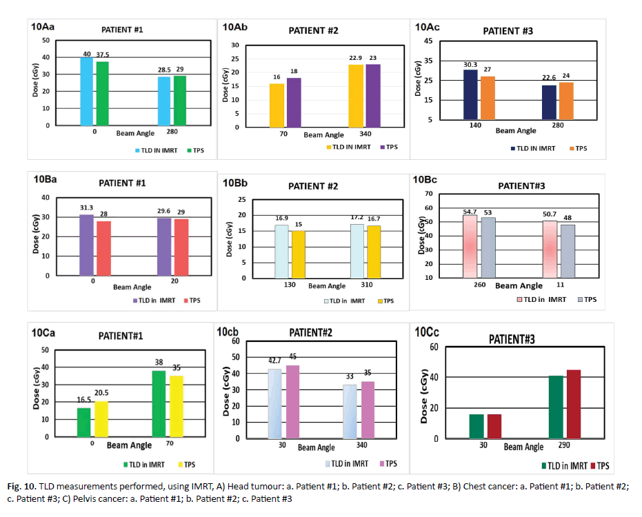
Figure 10. TLD measurements performed, using IMRT, A) Head tumour: a. Patient #1; b. Patient #2; c. Patient #3; B) Chest cancer: a. Patient #1; b. Patient #2; c. Patient #3; C) Pelvis cancer: a. Patient #1; b. Patient #2; c. Patient #3
TLD in IMRT for chest
The results of using TLD in IMRT technique for chest cancer are described in (Tables 9-11). In the first patient, at beam angle 0° the TLD reading was 31.3 cGy but TPS reading was 28 cGy with a percentage difference of 11.78%. In the second beam 20°, TLD measurements was 29.6 cGy while the reading of TPS was 29 cGy with a percentage difference of 2.06%. The average deviation for patient #1 was 6.92%. In the second patient, at beam angle of 130° measured by TLD the dose reading was 16.9 cGy while TPS reading was 15 cGy providing a percentage deviation of 12.66%. In the second beam at angle of 310°, the TLD reading was 17.2 cGy while TPS recorded a value of 16.7 cGy yielding a percentage deviation of 2.99%. The average deviation for patient #2 was 7.82%. In the second patient, at beam angle of 130° measured by TLD the dose reading was 16.9 cGy while TPS reading was 15 cGy providing a percentage deviation of 12.66%. In the second beam at angle of 310°, the TLD reading was 17.2 cGy while TPS recorded a value of 16.7 cGy yielding a percentage deviation of 2.99%. The average deviation for patient #2 was 7.82%. In the third patient, at beam angle of 260° TLD measurement was 54.7 cGy while that TPS was 53 cGy the difference between IMRT and TPS approximately was 3.20%, (Figure 10B).
| CHEST | Number of cases | Angle | Average dose 3 points TLD | Average dose (TPS) | Deviation % (TLD-TPS/TPS) |
|---|---|---|---|---|---|
| 0 | 31.3 | 28 | 11.78 | ||
| Patient#1 | 200 | 29.6 | 29 | 2.06 | |
| Average Deviation patient  = +6.92 % | |||||
| 1300 | 16.9 | 15 | 12.66 | ||
| Patient#2 | 3100 | 17.2 | 16.7 | 2.99 | |
| Average Deviation patient =+7.82 % | |||||
| 2600 | 54.7 | 53 | 3.2 | ||
| Patient#3 | 110 | 50.7 | 48 | 5.62 | |
Average Deviation patient =+4.41 %
Average Deviation for Three Patients of Chest =+6.38 %
Table 11. Average dosimetry of used Three TLD for each case IMRT chest cancer, compare it with three point in TPS, and take average for it
TLD in IMRT for pelvic
Results of using TLD in IMRT technique for pelvic cancer (Table 10). In the first patient of pelvic tumour at beam angle 0° by TLD was 16.5 cGy while by TPS was 20.5 cGy and percentage deviation of 19.51%. In the second beam angle at 70° measured dose by TLD was 38 cGy but by TPS was 35 cGy with a difference of 8.57%.
The average deviation for patient #1 was 14.04%. In the second patient of pelvic cancer at beam angle 300° measured dose by TLD was 42.7 cGy but by TPS was 45 cGy and the percentage deviation was 5.11%.
At beam angle of 340°, TLD was 33 cGy but TPS reading was 35 cGy with a deviation of 5.71%. The percentage deviation for patient #2 was 5.41%. In the third patient of pelvic tumour at beam angle 300°, TLD was 15.9 cGy while by TPS was 16 cGy with percentage deviation of 0.62%. In the second beam at angle 290° measured dose by TLD was 41 cGy whereas by TPS the reading was 45 cGy with a percentage difference of 8.88%. The average deviation for patient #3 was 4.75% (Tables 9 and 12 and Figure 10C).
| PELVIC | Number of cases | Angle | Average dose 3 points TLD | Average dose 3 points TPS | Deviation % (TLD-TPS/TPS) |
|---|---|---|---|---|---|
| Patient#1 | 0 | 16.5 | 20.5 | -19.51 | |
| 700 | 38 | 35 | 8.57 | ||
| Average Deviation Patient#1= ±14.04 % | |||||
| Patient#2 | 300 | 42.7 | 45 | -5.11 | |
| 3400 | 33 | 35 | -5.71 | ||
| Average Deviation Patient #2=Â ? 5.41 % | |||||
| Patient#3 | 300 | 15.9 | 16 | -0.62 | |
| 2900 | 41 | 45 | -8.88 | ||
Average Deviation Patient #3=Â ? 4.75 %
Average Deviation for three patients of pelvic= ± 8.06 %
Table 12. Average dosimetry of used Three TLD for each case IMRT pelvic cancer, compare it with three point in TPS, and take average for it
Discussion
Kadesjö, et al. indicated the diode dosimetry performed for treatments was good 92.2% of the measurements showed deviations within ± 5% of the expected values [11]. Because of the good agreement between measured and calculated values they presented method, it is possible to implement diode based in vivo dosimetry as a routine procedure in step-and-shoot IMRT, this is in line with our results [11].
When looking at all measurements, for three clinical sites (brain, chest, pelvic), 97% were within ± 2% of the calculated value. In the head region we observed the partially blocking segments effected on phantom plans 3.97% while on patient 5.18%. Deviation for chest on phantom was 2.65% but on patient was 5.69%. Deviation in the pelvic was 4.01% on the phantom, whereas deviation on the patient was 5.60%.
The present results contrast to the results achieved by Laojunun, et al. reported the diode is not efficient and not valuable tool for IMRT QA at different degrees of gantry angles [12].
This is identical to the study by Higgins et al [13], where they concluded that diodes provide one method of achieving link between the detailed phantom measurements and in vivo actual treatment situation to IMRT quality assurance. Spatially in high-energy photons may the measurements different by more than 10% from the calculated value. These variation in dose are causing increased secondary radiation to tissues outside the treated area from leakage and scatter, as well as a possible increase in the neutron dose from photon interactions in the machine head [13].
In scatter dose reaching to the diodes with segments partially irradiating the diode there is an appreciable uncertainty in diode response and a 5% to 10% difference between measured and calculated doses. This is consistent with article by Alaei et al. [14], who concluded that.
From the results we found that using diode in VMAT was not valid at different rotation beam angles because volumetric arc and radiation was delivered while the gantry rotates around the patient and dose rate can be continuously varied to deliver the prescribed dose to the planning target volume. Nevertheless, diode is valuable tool for VMAT QA at zero-degree gantry, the results were in concordance to the studies reported by Laojunun, et al. [12], the dose at the target in VMAT technique has relative deviation tend to greater than dose deviation of IMRT technique. The hypothesis of this phenomenon is the difference fluence of VMAT happens during the treatment that means the detectors received the difference fluence during the measurement compared to IMRT technique. It means the point of the detector received difference fluence during the measurement, so it can be a source of higher uncertainties of the measurement during VMAT techniques respectively and consistent with other studies by Slusarczyk-kacprzyk, et al. [15].
The results of TLD in IMRT is less accurate than that for VMAT distribution especially at the edges. The penumbra edges have a percentage difference of 20% and ±10% while it’s very close to zero at the middle region. This is identical to the study by ur Rehman, et al. [16], where they concluded that the TLD is feasible QA tool for VMAT plan.
In the second beam at 110° measured by TLD was 50.7 cGy but TPS reading was 48 cGy providing a percentage different of 5.62%, the average deviation for patient #3 was 4.41% that consistent with other studies by Nailon et al. [17].
Slusarczyk-kacprzyk et al. evaluated the TLD dosimeters type of (Li-F MT-F) were mailed to each participant [15]. The participants were instructed to irradiate three TL detectors for each beam with a dose of 2 Gy in reference conditions. They concluded deviations larger than 3.5% were observed for 5 beams in 5 radiotherapy centers. For one photon beam the deviations were between 3.5% and 5%, while for four photon beam they were larger than 5% (from 5%, 3% to 30,1%). Rehman et al. sated Imaging and Radiation Oncology Core Houston (IROC-H) head and neck phantom with Thermo- Luminescent Dosimeters (TLDs), films were image with computed tomography scan, and the reconstructed image was transfer to pinnacle Treatment-Planning System (TPS) [16], and the Planning Target Volume (PTV), Secondary Target Volume (STV) and Organ At Risk (OAR) were delineate manually and a treatment plan was made [16].
Najem et al. they verified using six IMRT and seven VMAT plans on up to three different phantoms. The method’s sensitivity and accuracy were investigated by introducing errors [18].
Conclusion
Differences in the results between the head and the chest and the pelvic measurements but there is a wider distribution for the pelvic cases. This may be partially due to the placement of diode at large separation.
References
- Marajh C. Anatomy of an error: cancer treatment radiation overdose. J Trinidad Express Newspapers. 2011;41:72-103.<
- Holmberg O, Coffey M, Knöös T, Cunningham J. ROSIS-Spotlight on in-vivo dosimetry. J Radiother Oncol. 2016;97:601-710.<
- IAEA Human Health Reports. Development of procedures for in vivo dosimetry in radiotherapy. IAEA. 2013;8:170-179.
- Harrison R, Morgan A. In vivo dosimetry: hidden dangers?Br J Radiol. 2007;80:691-692.
- Kinhikar R, Chaudhari S, Kadam S, Dhote D, Deshpande D. Dosimetric validation of new semiconductor diode dosimetry system for intensity modulated radiotherapy.J Cancer Res Ther. 2012;8:86-90.
- Morin J, Beliveau-Nadeau D, Chung E. A comparative study of small field total scatter factors and dose profiles using plastic scintillation detectors and other stereotactic dosimeters: the case of the Cyber Knife.Med Phys.2013;40:011719.
- Dipasquale G, Nouet P, Rouzaud M, Dubouloz A, Miralbell R, et al. In vivo quality assurance of volumetric modulated arc therapy for ano-rectal cancer with thermoluminescent dosimetry and image-guidance.Radiother Oncol. 2014;111:406-411.
- Gee HE, Bignell F, Odgers D, Gill S, Martin D, et al. Breast tissue expanders: in vivodosimetry. J Med Imag Radiation Oncol. 2016;60:138-145.
- Maulana A, Pawiro SA. Dosimetry verification on VMAT and IMRT radiotherapy techniques: In the case of prostate cancer. J Phys Conf Ser. 2016;694:10-20.
- Pepele EK. An experimental study on the determination of gantry angle and SSD dependencies of TLD and MOSFET dosimeter systems. Int J Radiat Res. 2017;15:117-121.
- Kadesjö N, Nyholm T, Olofsson J. A practical approach to diode based in vivo dosimetry for intensity modulated radiotherapy.Radiother Oncol. 2011;98:378-381.
- Laojunun P, Iampongpaiboon P, Kakanaporn C, Tuntipumiamorn L, Chansilpa Y. Evaluation of planar and cylindrical diode arrays for IMRT and VMAT plan verification. J Challenge of QA Radial Med. 2012;35:73-76.
- Higgins PD, Alaei P, Gerbi BJ, Dusenbery KE. In vivo diode dosimetry for routine quality assurance in IMRT.Med Phys. 2003;30:3118-3123.
- Alaei P, Higgins PD, Gerbi BJ. In vivo diode dosimetry for IMRT treatments generated by pinnacle treatment planning system.Med Dosim. 2009;34:26-29.
- Slusarczyk-kacprzyk W, Bulski W, Ulkowski P, Chelminski K. Postal TLD dosimetry audits in radiotherapy in Poland-Results of 2017. J Med Phys. 2018;52:1-145.<
- RehmanJ,IsaM,AhmadN.Quality assurance of volumetric-modulated arc therapy head and neck cancer treatment using PRESAGE® dosimeter.J Radiother Pract. 2018;17:441-446.
- Nailon WH, Welsh D, McDonald K. EPID-based invivo dosimetry using dosimetry check™: overview and clinical experience in a 5-yr study including breast, lung, prostate, and head and neck cancer patients. J Appl Clin Med Phys. 2019;20:6-16.
- Najem MA, Tedder M, King D. In-vivo EPID dosimetry for IMRT and VMAT based on through-air predicted portal dose algorithm.Physica Medica. 2018;52:143-153.


Editors List
-
RAOUi Yasser
Senior Medical Physicist
-
Ahmed Hussien Alshewered
University of Basrah College of Medicine, Iraq
-
Sudhakar Tummala
Department of Electronics and Communication Engineering SRM University – AP, Andhra Pradesh
-
Alphonse Laya
Supervisor of Biochemistry Lab and PhD. students of Faculty of Science, Department of Chemistry and Department of Chemis
-
Fava Maria Giovanna
Google Scholar citation report
Citations : 558
Onkologia i Radioterapia received 558 citations as per Google Scholar report
Onkologia i Radioterapia peer review process verified at publons
Indexed In
- Directory of Open Access Journals
- Scimago
- SCOPUS
- EBSCO A-Z
- MIAR
- Euro Pub
- Google Scholar
- Medical Project Poland
- PUBMED
- Cancer Index
- Gdansk University of Technology, Ministry Points 20
